
Solvent Recovery Engineering Guide
Vapor Phase VOC Recovery & Emission Control
DEC.SRU™ ♻️ Solvent Recovery | Solvent Recovery Units, Systems & Plants
Direct Answer: A Solvent Recovery Unit (SRU) is a vapor-phase VOC recovery system that uses activated carbon adsorption to capture 95-99% of solvents from industrial exhaust air. It works in a continuous 4-stage cycle - adsorption, bed switching, desorption with nitrogen/steam/vacuum, and condensation - to recycle solvents for reuse, achieve <50 mgC/m3 emissions (or lower) and meet EU BAT/BREF/IED and US EPA compliance while delivering 12-36 month ROI vs RTO destruction.
Solvent Recovery Units (SRUs) — also known as Solvent Recovery Plants (SRP), Solvent Recovery Systems (SRS), solvent vapor recovery systems, or generically as industrial solvent recovery systems, solvent recovery solutions and VOC recovery solutions — are vapor phase solvent recovery systems: vapor phase industrial air pollution control (APC) equipment used to capture, concentrate and recycle VOC solvents exhausted from industrial processes via the solvent recovery process: adsorption, desorption, condensation and purification. A well-designed SRU reduces VOC emissions to comply with environmental regulations, recovers solvent for reuse, and lowers the net cost of solvent consumption over the life of a plant. This page is a complete engineering reference: it explains how solvent recovery works from first principles, how to select between regeneration technologies, how to evaluate solvent-by-solvent recoverability, how SRUs compare with thermal and biological VOC abatement technologies, how to size and specify a system, and how to remain compliant with BAT/BREF, IED and EPA requirements. DEC has engineered and delivered Solvent Recovery Units since 1946 (Milan, Italy), building on an activated-carbon solvent recovery technology lineage that traces back to the 1920s, including engineering milestones such as the first activated-carbon steam-regenerated SRU for the flexible packaging industry (early 1970s, recovering ethyl acetate) and the first activated-carbon nitrogen-regenerated SRU, DEC.SRU_RSG™ (1980s). The explanations below reflect that applied engineering experience, carried out today by a global workforce of chemical, mechanical, electrical, environmental and civil engineers operating under ISO 9001-certified quality management across 2,500+ delivered projects.
Executive Summary
This engineering guide explains the solvent recovery process and how Solvent Recovery Units — vapor phase solvent recovery systems also known as solvent vapor recovery systems, industrial solvent recovery systems, solvent recovery solutions and VOC recovery solutions — work, when activated-carbon recovery outperforms thermal oxidizers and other VOC abatement/VOC recovery technologies, which solvents can (and cannot) be recovered, the efficiencies and stack emission levels achievable, and the CAPEX/OPEX, environmental-compliance and safety-engineering factors that drive technology selection. It covers the four-stage adsorption/desorption/condensation cycle at the core of every carbon-based SRU; the three regeneration technologies — nitrogen, steam and vacuum — and the solvent chemistry, utility availability and safety considerations that determine which one fits a given application; a solvent-by-solvent compatibility guide for 17 commonly recovered solvents plus halogenated solvents as a separate case; and a like-for-like comparison of activated carbon adsorption against RTO, DTO, CTO, direct condensation, liquid scrubbing, biofiltration and membrane separation, including where hybrid concentrator/SRU or concentrator/oxidizer configurations make sense. Engineering design sections address airflow and turn-down sizing, humidity, temperature, fouling, corrosion, and cooling-system selection; economics sections cover CAPEX, OPEX, ROI and payback logic; compliance sections map BAT/BREF, IED and EPA regulatory frameworks to system design; and safety-engineering sections cover ATEX/explosion prevention, oxygen and LEL monitoring, fire protection, redundancy and site-layout risk, drawing on independent property-risk-engineering guidance (AXA XL, FM Global) alongside regulatory sources. The guide closes with digitalization/Industry 4.0 practice, DEC's SMS™/CBS™ product range, 60+ FAQs, a 100+ term glossary, and a full bibliography. It is written for process, environmental and EHS engineers, plant managers and risk/insurance engineers evaluating, specifying or auditing a Solvent Recovery Unit.
Key Engineering Takeaways
- SRUs recover, not destroy: activated-carbon adsorption reclaims solvent for reuse, unlike RTO/DTO/CTO thermal oxidation, which converts VOC to CO₂ and water (see §4).
- Recovery efficiency: up to ~99% of solvent input, with TVOC stack values as low as ≤50 mgC/m³ (≤20 mgC/m³ with DEC.ULE™) achievable (see §1).
- Three regeneration technologies — nitrogen (steamless/dry), steam, and vacuum — each suit different solvent chemistries, site utilities and safety profiles; the choice drives CAPEX, OPEX and recovered-solvent purity (see §9).
- Water solubility and flammability, not boiling point alone, are the primary drivers of regeneration-technology selection (see §9.4).
- Not every solvent is safely recoverable: some solvents are flagged in risk-engineering literature as prone to breakdown under adsorption/desorption conditions; DEC manages risk via nitrogen regeneration rather than avoiding it (see §5).
- Two or more adsorber beds are required for continuous operation — one adsorbs while the other regenerates (see §1.2).
- Carbon bed fire protection uses nitrogen inertization preferred to overbed water deluge (see §13.4).
- Regeneration energy demand is the primary operating-cost driver: advanced energy-recovery processes such as DEC.THRx™ and DEC.ULP™ can reduce energy demand for inert-gas regeneration by up to 40%, while ECOVAP™ can decrease thermal energy demand for steam-regenerated systems from the historical ~3–4 t steam/t solvent to approximately 2 t/t solvent or less (see §10).
- Non-regenerative (throwaway) adsorbers are typically only economical below roughly 10 tonnes/year of total VOC mass loading; above that, a regenerative SRU generally wins on lifecycle cost (see §4.3).
1. What is a Solvent Recovery Unit? Engineering Fundamentals
1.1 Definition
A Solvent Recovery Unit (SRU) — interchangeably called a Solvent Recovery Plant (SRP) or Solvent Recovery System (SRS) (see DEC's terminology explainer on how these terms relate to Solvent Reclaiming Equipment, SRE) — is an industrial air pollution control system that removes volatile organic compounds (VOCs) from a solvent-laden air (SLA) exhaust stream, concentrates them on a sorbent (typically activated carbon), and desorbs them in a form that can be condensed and reused as liquid solvent. Unlike destructive VOC abatement technologies that oxidize solvent into CO₂ and water, a Solvent Recovery Unit is a recovery, not a destruction, technology: the solvent is preserved as a saleable or reusable product.
1.2 The Solvent Recovery Process: How Activated Carbon Solvent Recovery Works — The Four-Stage Cycle
Every carbon-based SRU operates on a repeating four-stage cycle split across at least two adsorber vessels, so that one vessel can adsorb while the other regenerates:

- Adsorption: solvent-laden air passes through a fixed bed of activated carbon; VOC molecules are physically retained (adsorbed) onto the internal pore surface of the carbon by van der Waals forces, while clean air exits the bed and is discharged to the stack or recirculated to the process.
- Bed switching: once a bed approaches its designed breakthrough point (see §8.4), the process air is automatically switched to a second, regenerated bed so that adsorption is continuous while the first bed is regenerated.
- Desorption (regeneration): the loaded bed is stripped of solvent using nitrogen, steam, or hot air/vacuum (see §9), reversing the adsorption equilibrium and releasing a concentrated solvent vapor stream.
- Condensation & recovery: the desorption vapor is cooled in a condenser (direct or indirect, sometimes assisted by refrigeration, brine cooling, or — for particularly stringent residual-emission targets — cryogenic condensation) until the solvent condenses to liquid; if immiscible with water, it is separated by decantation — laminar-flow decanter design, rather than turbulent flow, measurably improves recovered-solvent clarity and reduces emulsion formation at the water/solvent interface — and if miscible, it may require downstream purification (dehydration and/or distillation) to reach the target purity for reuse.
1.3 Adsorption Principles
Adsorption is a surface phenomenon: gas-phase VOC molecules migrate to and are held on the internal surface of a porous solid (the adsorbent) without a chemical reaction taking place. The driving force is the equilibrium partitioning of the VOC between the gas phase and the adsorbed phase, described by adsorption isotherms (e.g., Freundlich or Langmuir-type relationships) that link adsorbed quantity to gas-phase concentration at constant temperature. Physical adsorption (physisorption) is reversible, which is what allows the same carbon bed to be loaded and regenerated thousands of times over its service life. Key variables governing adsorption performance include the carbon's pore size distribution relative to the VOC molecule size, the VOC's molecular weight and polarity, gas velocity through the bed, temperature, and relative humidity of the inlet air.
1.4 Desorption Principles
Desorption is the reverse process: energy is supplied (as heat - TSA, or combined heat and reduced pressure T+VSA) to shift the adsorption equilibrium so VOC molecules leave the carbon surface and return to the gas phase at a much higher concentration than in the original SLA stream. Because desorption reconcentrates the VOC by a large factor (commonly 10–50×, depending on regeneration method and solvent), it enables efficient downstream condensation with a comparatively small heat-exchange duty. Complete desorption is neither achievable nor necessary in practice: a carbon bed retains a "heel" of residual solvent (working capacity is discussed in §8.5), and regeneration is optimized around economic and safety criteria rather than 100% removal.
1.5 Condensation & Solvent Purification
The desorbed vapor stream is condensed to recover liquid solvent. Water-immiscible solvents (e.g., toluene, xylene, hexane) separate cleanly from any condensed process water by gravity in a decanter. Water-miscible solvents (e.g., ethanol, IPOH, acetone, THF) condense together with any process moisture picked up during regeneration, and typically require a downstream separation step — often a dehydration module and/or distillation — to reach a purity suitable for reuse in the originating process. Miscibility alone does not tell the whole story: many solvents form azeotropes — binary (solvent–water) or ternary (solvent–solvent–water, or solvent–solvent) mixtures that boil at a constant composition and cannot be separated by straightforward distillation — so purification design must check the full azeotrope behavior of the recovered mixture, not just whether the solvent is nominally miscible or immiscible with water. Where a problematic azeotrope exists, options include molecular-sieve-based dehydration, pressure-swing distillation (DST-p or DST-v), each selected based on the specific binary or ternary system involved, or entrainer-assisted (azeotropic/extractive) distillation (DST-e). A concrete, well-documented illustration of how quickly this becomes a real constraint rather than a theoretical one: ethyl acetate and water form a binary azeotrope boiling at roughly 70.4°C, at a fixed composition of about 91.5% ethyl acetate to 8.5% water — meaning a wet ethyl acetate stream cannot simply be distilled down to anhydrous solvent past that composition; the azeotrope itself has to be removed overhead and phase-split again to make further progress. Adding a second solvent narrows the achievable purity further still: an ethyl acetate/ethyl alcohol/water blend forms a ternary azeotrope boiling at roughly 70.2°C (approximately 82.6% ethyl acetate, 8.4% ethyl alcohol, 9.0% water), on top of the additional binary azeotropes each pair of these three components forms with each other — illustrating, concretely, why a recovered-solvent stream containing more than roughly single-digit percentages of a second, water-miscible co-solvent and water together can become genuinely difficult to purify by straightforward distillation, rather than merely "needing a slightly bigger column."
Recovered-solvent purity, not just recovery efficiency, is therefore a key design parameter: a plant with 99% VOC capture is only as useful as the reusability of what comes out the other end. As an illustration of what a well-run multi-solvent recovery/distillation train can achieve in practice, documented industrial operating data for solvents including MEK, toluene and cyclohexanone show recovered-solvent GC purity in the 98.5–99%+ range, residual water in the 0.05–0.10% range, and acidity (as acetic or adipic acid, from trace hydrolysis/oxidation byproducts — see §8.6) held below roughly 0.003–0.02%, at a mass-recovery rate close to 100% of net applied solvent — figures worth requesting from a vendor as a specification target and verification benchmark, not just a recovery-efficiency percentage. As a specific illustration of what a well-designed nitrogen-regenerated system can hold to in practice, documented DEC plant performance data for ethyl-acetate-based and mixed MEK/ethyl-acetate/ethanol streams shows recovered-solvent water content below 0.1% (typically averaging around 0.05%) and acetic acid content likewise below 0.1% (typically averaging around 0.05%) — consistent with, and reinforcing, the essentially-eliminated hydrolysis discussed in §8.6 for dry, nitrogen-regenerated service.
1.6 Closed-Loop Recovery Systems
In a closed-loop configuration, the regeneration inert gas (typically nitrogen) is continuously recirculated between the carbon bed, the condenser and back to the bed heater, with no gas vented to atmosphere during desorption. Closed-loop nitrogen systems allow near-total oxygen exclusion, which is important both for solvent stability (many recovered solvents are prone to oxidation) and for keeping the regeneration atmosphere outside the flammable range even at high VOC concentration. Closed-loop design is the basis of nitrogen (inert gas) regeneration systems and is discussed in detail in §9.1.
1.7 Dehydration Sequencing: First-Phase (Gas-Phase) vs. Second-Stage (Liquid-Phase) Dehydration
Where water is removed from the process matters as much as whether it is removed at all, for two independent reasons: energy consumption and byproduct contamination. It is useful to think of dehydration as happening in up to two distinct phases: a first-phase, gas-phase pre-dehydration step, acting on the regeneration vapor before or during condensation, and a second-stage, liquid-phase dehydration step, acting on the already-condensed liquid solvent.
First-phase (gas-phase) pre-dehydration. Rather than only dehydrating the liquid condensate after desorption and condensation are already complete, some SRU designs selectively remove water while the stream is still in the gas/vapor phase, before it reaches that later liquid-phase step. DEC implements this first phase through three related technologies — DEC.ADM_PHD™ (Pulse Heat Dehydration), DEC.ADM_FDP™ (Fractional Dehydration Process) and the gas-phase DEC.ADM_MSU™ (Molecular Sieve Unit), suited to more complex mixed-VOC streams that include ketones — all acting during carbon regeneration itself and driven by the same underlying Kinetic Desorption Algorithm (DEC.KDA™), further tuned by AI/ML, which selectively isolates and condenses water vapor separately from the target solvents. In both cases, the underlying principle is the same: removing water while still in the gas phase reduces the water load that the rest of the process (condensation, and any second-stage dehydration) has to handle, which can lower overall energy consumption and reduce or eliminate the need for a downstream second-stage dehydration step entirely. Pre-dehydration is different from condensing moisture as a preliminary step and then re-evaporating it elsewhere in the air-handling train, which involves two separate phase-change energy penalties (condensation, then re-evaporation) instead of one, and can introduce a mildly acidic, solvent-contaminated water stream (e.g., containing trace acetic acid from ester hydrolysis) into ductwork or filter housings usually not designed for corrosion resistance.
Second-stage (liquid-phase) dehydration and its placement relative to distillation. Where a first-phase step is not sufficient on its own — or is not present — a second-stage, liquid-phase dehydration step [e.g. a DEC.ADM_UDS™ (Ultra-Dehydration System) type module using molecular sieves] removes the remaining water from the already-condensed liquid solvent. When this second-stage dehydration is used ahead of a multi-column distillation train, sequencing still matters within the liquid phase: molecular sieves can act as a mild catalyst supporting the hydrolysis of the processed solvents. Placing the second-stage dehydration step before the full distillation train, rather than between distillation columns, keeps any acid generated out of the distillate light stream and avoids pure solvent contamination. Removing water ahead of distillation also means the columns are fed an already-dry mixture, which is more thermally efficient than distilling a wetter feed and dehydrating partway through the train.
2. Why Recover Solvents? The Environmental and Economic Case
2.1 Environmental Benefits
Solvent recovery directly reduces VOC emissions to atmosphere, which lowers ground-level ozone and photochemical smog formation, reduces exposure to hazardous air pollutants (HAPs) for surrounding communities, and supports compliance with increasingly strict emission limit values under frameworks such as the EU Industrial Emissions Directive (IED) and US EPA regulations (see §12). Because the process recovers material rather than destroying it, it also avoids the combustion-related CO2, NOx and fossil fuel (e.g. natural gas, CH4) consumption associated with thermal oxidation, giving solvent recovery a favorable position in most carbon-footprint comparisons versus destructive VOC abatement.
2.2 Economic Benefits
Recovered solvent directly offsets the cost of virgin solvent purchases, which is often the single largest driver of payback for an SRU (see §11.4). In processes with high solvent consumption — printing, coating, flexible packaging, battery electrode manufacturing — solvent purchase cost can dwarf both the CAPEX and OPEX of the recovery system, making the investment case straightforward once yearly solvent throughput crosses a facility-specific threshold.
2.3 Circular Economy & Decarbonization
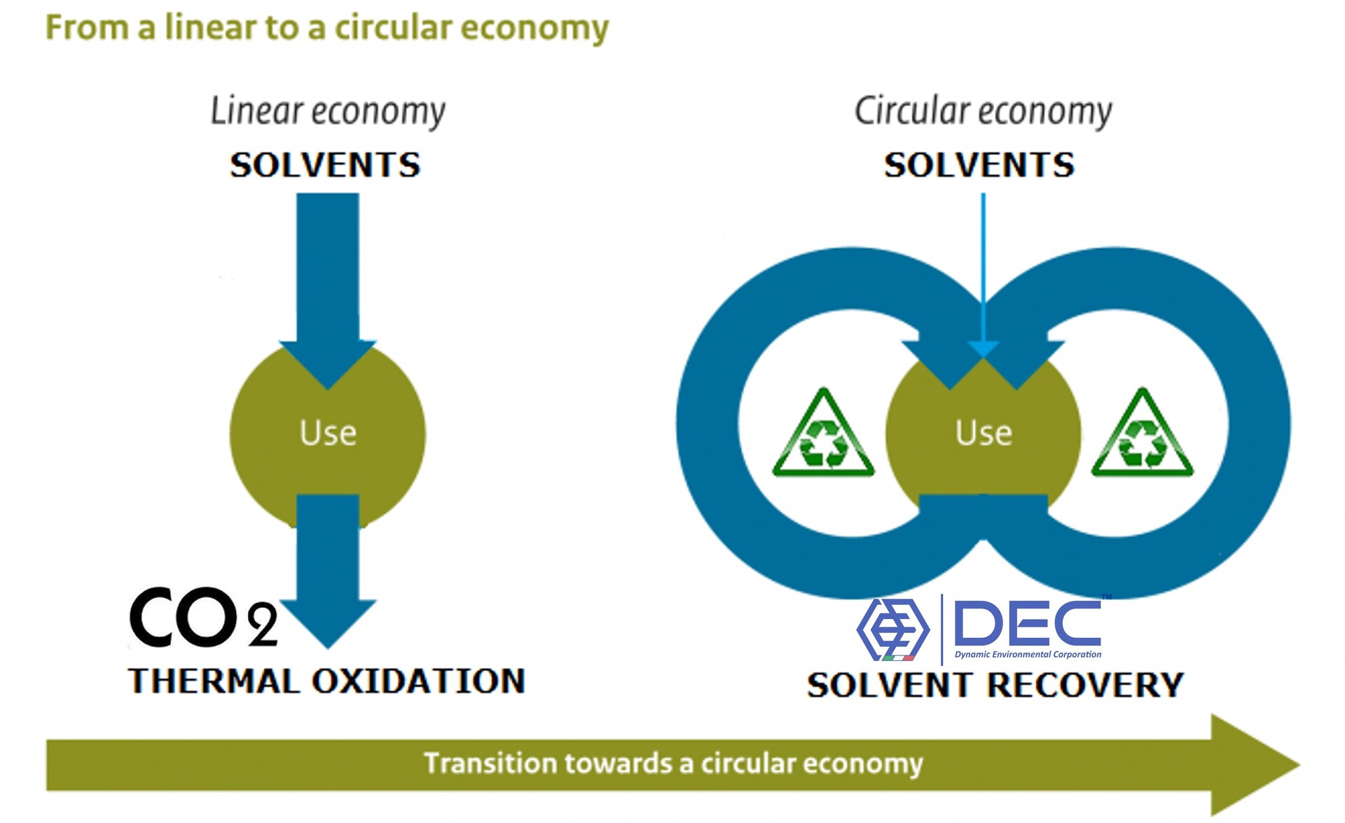
Solvent recovery is a textbook circular-economy technology: instead of a linear "purchase virgin solvent → emit / incinerate" model, the solvent is captured, purified, and returned to the same process, cutting both upstream extraction/production emissions embedded in virgin solvent and downstream emissions from destruction technologies. For companies with ESG or net-zero commitments, SRUs are frequently one of the highest-return decarbonization investments available at a process-emissions level, because the reduction in purchased solvent is measurable, auditable, and directly tied to a cost saving rather than only a compliance cost. A rigorous comparison against thermal destruction should account for full lifecycle (Scope 3) emissions, not only the facility's own direct combustion emissions: producing and transporting virgin replacement solvent for a destroyed VOC stream carries its own upstream CO2 footprint, which recovery avoids by keeping the same solvent molecules in use rather than requiring new solvent to be manufactured and shipped in. Published industry case studies applying this full lifecycle accounting to high-value solvents such as toluene have reported substantially lower total CO2e for recovery than for oxidation once virgin-solvent production and logistics are included, alongside sub-one-year payback periods driven by avoided solvent purchase — illustrating that the economic and environmental cases for recovery tend to move together rather than trading off against each other for commodity, high-value solvents (see References, §18).
2.4 Waste Reduction
Beyond air emissions, solvent recovery reduces the volume of spent-solvent waste that would otherwise require off-site disposal or incineration as hazardous waste, lowering waste-handling costs and the regulatory burden associated with hazardous-waste manifesting and transport.
3. Selection Criteria for a Solvent Recovery Unit
When selecting a Solvent Recovery Unit, there are several factors to consider, including:
- The SLA (Solvent-Laden Air) volume that needs to be treated by the VOC emission control system;
- The type of solvents (within chemicals and/or dilutants) being used and their breakdown;
- The yearly volume of solvent being used at site;
- The demanded stack emission limit, in order to comply with applicable local environmental regulations;
- The budget (CAPEX);
- Performance KPIs to specify and verify with the vendor — solvent recovery rate (see glossary), VOC removal efficiency, recovered-solvent purity, specific energy consumption per kg of solvent recovered, and operational stability under variable/turn-down loading (see §7.1) — rather than a single headline efficiency figure;
- The vendor's after-sales capability — preventive/corrective maintenance, operator training, remote monitoring and diagnostics, and revamping/retrofit support for existing installations (see §11.3) — since long-term performance depends as much on ongoing support as on initial engineering (industry surveys of the flexible-packaging printing sector have found a substantial share of the installed SRU base predates 2000, with energy consumption and operating cost cited as the leading concern by a large majority of operators, underscoring how much value well-planned revamping can unlock on older plants);
- Technology roadmap and future readiness — whether the vendor's platform supports hybrid configurations (adsorption plus dehydration/distillation, see §4.2), Industry 4.0 connectivity (see §14), and capacity expansion without a full plant redesign.
3.1 Decision Tree: Which VOC Treatment Technology Should I Choose?
The flow below distills the selection criteria above into a sequential decision path — a fast way to reach a shortlist before working through the detailed comparison in §4 and the quick decision matrix in §4.0.
| Step | Question | If the answer points this way… | …consider |
|---|---|---|---|
| 1 | Is the VOC-laden air stream large-volume and dilute (low mg/Nm³), or already concentrated? | Large volume, dilute | An upstream concentrator (rotary/static/fluidized bed) ahead of whichever final abatement technology is selected below, to shrink the airflow the final equipment must handle |
| 2 | Does the solvent have meaningful reuse or resale value, and is it chemically recoverable (see §5 for solvents that are difficult or unsafe to recover)? | No reuse value, or not safely recoverable | Destructive abatement: RTO, DTO or CTO (§4); biofiltration if the VOC is biodegradable and concentration is low |
| Yes, has reuse value and is recoverable | Continue to Step 3 — activated-carbon Solvent Recovery Unit | ||
| 3 | Is total annual VOC mass loading above or below roughly 10 tonnes/year (see §4.3)? | Below ~10 t/yr | A non-regenerative (throwaway) carbon adsorber may be more economical than a full regenerative SRU |
| Above ~10 t/yr | A regenerative SRU is generally the better lifecycle-cost choice — continue to Step 4 | ||
| 4 | Is the solvent water-miscible, and is low-cost steam already available on-site (see §9.4)? | Water-immiscible, steam available | Steam regeneration (RSV™) |
| Water-miscible, flammable, oxidation- or peroxide-sensitive, or no on-site steam | Nitrogen (inert-gas) regeneration (RSG™) | ||
| High-boiling or heat-sensitive solvent (e.g., NMP, DMF, cyclohexanone) | Vacuum regeneration (RTV™) | ||
| 5 | Does the permit require ultra-low emissions (below the standard ≤50 mgC/m³ TVOC target)? | Yes, ≤20 mgC/m³ or lower | Add a polishing stage such as DEC.ULE™ downstream of the SRU |
| 6 | Does the process involve flammable, oxidation-sensitive, or otherwise higher explosion-risk solvents? | Yes | Confirm regeneration-technology choice against Safety Engineering (§13) — LEL/MOC monitoring, ATEX zoning, fire protection — before finalizing the design, not after |
This decision tree is a starting heuristic for shortlisting, consistent with — but not a replacement for — the full solvent-by-solvent, site-specific engineering evaluation described throughout this guide.
DEC offers a variety of Solvent Recovery Units (SRUs) to meet the needs of different industrial applications: the processes are safe and very efficient, allowing the recovery a wide range of solvents.
Here are some of the benefits of using a DEC.SRU™ (Solvent Recovery Unit):
- most referenced: DEC is rooted back in 1946, the most-referenced, with a succesful delivery of thousand of installations worldwide, tracing back to the world's first activated-carbon solvent recovery plant for the flexible packaging industry — recovering ethyl acetate via the steam-regenerated DEC.SRU_RSV™ process — which began operating in Italy in 1972;
- award winning innovations, effective design, for fitting specific and/or and high demanding tasks;
- different configurations and flexible layouts: SMS™ (Smart Modular Systems) to CBS™ (Custom Built Systems);
- compliance with global environmental regulations and VOC emissions standards: TVOC values down to ≤ 50 mgC/m3 (or ≤ 20 mgC/m3, for SRUs equipped with DEC.ULE™);
- high recovery rates: DEC Solvent Recovery Units can recover up to 99% of the solvent input;
- easy to maintain and operate;
- low operating costs (OPEX): the activated carbon on-site regeneration process is a low-cost way to regenerate the adsorbent;
- full-electric version available (e-SRU™);
- environmentally friendly: Solvent Recovery Units can help to reduce VOC emissions, improve environmental compliance, including sustainability and net-zero targets;
- generate important savings (ROI, improving your bottom-line);
- guaranteed deliverables;
- extended warranty policies available;
- inspection and maintenance contracts, delivered through DEC SERVICE.
4. Technology Comparison: Activated Carbon Adsorption vs Thermal and Biological VOC Abatement
No single VOC abatement technology is universally optimal. The right choice depends on VOC concentration, solvent recoverability/value, flow rate, and whether the objective is recovery (recycling the solvent) or destruction (converting it to CO₂ and water). The table below compares the principal technologies on the criteria engineers actually use to shortlist a solution.
| Technology | Principle | Solvent recovery? | Typical VOC removal efficiency | Energy consumption | Best-fit VOC concentration | Typical OPEX driver | Best-fit applications |
|---|---|---|---|---|---|---|---|
| Activated Carbon Adsorption (SRU) | Physical adsorption + regeneration (N₂/steam/vacuum) + condensation | Yes — up to ~99% | 95–99% | Low–moderate (regeneration heat only) | Low–moderate (typically <5 g/Nm³, wide range with concentrators) | Carbon replacement, regeneration utilities | Printing, flexible packaging, coating, battery, pharma — where solvent has reuse value |
| Non-Regenerative (Throwaway) Carbon Adsorption | Physical adsorption, no in-place regeneration; spent carbon replaced when saturated | No — solvent leaves with spent carbon | 90–99%+ (until saturation) | None (no regeneration heating) | Low (best suited to low total annual mass loading, roughly <10 t/yr) | Carbon replacement & disposal/off-site regeneration | Low-emission sources, odor control, H₂S — where recovery value is absent or immaterial |
| Regenerative Thermal Oxidizer (RTO) | High-temperature oxidation with ceramic heat-recovery beds | No — destructive | 95–99%+ | Moderate (fuel for start-up/low-VOC support; can be autothermal at higher VOC loads) | Low–moderate | Natural gas, ceramic media replacement | Coating, printing lines without solvent-reuse economics |
| Direct Thermal Oxidizer (DTO) | Direct flame oxidation, no heat recovery media | No — destructive | >99% | High (continuous fuel firing) | Any, incl. very low | Continuous fuel consumption | Small/intermittent streams, high-destruction-efficiency mandates |
| Catalytic Oxidizer (CTO) | Oxidation over a catalyst bed at lower temperature than thermal | No — destructive | 90–98% | Low–moderate (lower temp than RTO/DTO) | Low–moderate; sensitive to catalyst poisons | Catalyst replacement, poisoning risk | Clean, poison-free VOC streams; moderate flows |
| Direct Condensation | Cooling/cryogenic condensation of solvent vapor | Yes | Variable — depends on solvent vapor pressure at achievable temperature | Moderate–high (refrigeration/cryogenics) | High (best on concentrated streams) | Refrigeration energy | High-concentration, near-saturated vapor streams; pre-concentration stage |
| Liquid Scrubbing / Absorption | VOC stripped from the gas phase into a liquid absorbent | Yes, for water-soluble solvents | Variable; multi-stage often needed for high efficiency | Low–moderate (pumping, no regeneration heat) | Moderate | Absorbent makeup, multi-stage equipment, scrubber-media biological growth control | Water-soluble solvents (e.g., alcohols (ROH)); less suited to water-immiscible VOCs |
| Biofilters / Bioscrubbers | Microbial degradation of VOCs on/through a biologically active media | No — destructive (biological) | 70–95% (compound-dependent) | Low | Low | Media replacement, moisture control | Odor control, biodegradable VOCs, wastewater treatment off-gas |
| Membrane Separation | Selective permeation of VOC vs air across a polymeric membrane | Yes (as a concentration/pre-concentration step) | Variable — often paired with condensation | Moderate (compression energy) | Moderate–high | Membrane replacement, compression energy | Vapor recovery (tank venting, loading operations) |
4.0 Quick Decision Matrix
Where the detailed table above compares technologies feature-by-feature, the matrix below scores each option 1 (poor fit) to 5 (excellent fit) against the four criteria engineers weigh most heavily when shortlisting — useful as a fast first pass, to be confirmed against the site-specific factors in §3 before final selection.
| Technology | Solvent value recovered | Fit for high VOC concentration | Fit for low VOC concentration | Relative OPEX | Relative CAPEX |
|---|---|---|---|---|---|
| Activated Carbon SRU (regenerative) | 5 | 3 | 4 | 3 | 3 |
| Non-Regenerative (Throwaway) Carbon | 1 | 2 | 5 | 2 | 5 |
| Regenerative Thermal Oxidizer (RTO) | 1 | 4 | 3 | 3 | 3 |
| Direct Thermal Oxidizer (DTO) | 1 | 5 | 2 | 1 | 4 |
| Catalytic Oxidizer (CTO) | 1 | 3 | 4 | 3 | 3 |
| Direct Condensation | 5 | 5 | 1 | 2 | 2 |
| Liquid Scrubbing / Absorption | 3 | 3 | 3 | 3 | 3 |
| Biofilters / Bioscrubbers | 1 | 1 | 4 | 5 | 4 |
| Membrane Separation | 4 | 4 | 2 | 2 | 2 |
Scores are directional engineering heuristics for first-pass shortlisting, not a substitute for the site-specific evaluation in §3 (SLA volume, solvent type and value, throughput, emission limit, CAPEX budget) or the detailed comparison table above.
4.1 When Does Recovery Beat Destruction?
Activated carbon adsorption is generally the preferred technology whenever the recovered solvent has meaningful reuse or resale value and the VOC concentration is compatible with adsorption (not so dilute that bed sizing becomes uneconomic, not so concentrated/near-saturated that explosion-safety margins dominate design). Thermal oxidation (RTO/DTO/CTO) becomes more attractive when the solvent mixture is too complex or contaminated to be usefully recovered, when no local reuse exists for the recovered solvent, or when destruction efficiency requirements are so stringent that recovery alone cannot guarantee compliance. In practice, many multi-line facilities use both: SRUs on lines with high-value, recoverable single solvents (e.g., toluene-based printing), and thermal oxidation on lines with complex or low-value solvent blends. Liquid scrubbing/absorption (see table above) is worth a closer look specifically where the target solvent is both highly volatile and water- or otherwise liquid-soluble: because the absorbent stripping step is a comparatively conventional distillation/stripping operation rather than a full carbon-bed thermal regeneration cycle, published industry comparisons have put its specific steam demand meaningfully below that of carbon adsorption for equivalent duty — an advantage worth weighing against scrubbing's other limitations (a taller, smaller-diameter stripping column than the absorber itself, a more restrictive choice of absorbent liquid to avoid azeotrope formation and excessive volatility, and generally poorer performance against very dilute or highly variable SLA streams than a carbon bed's inherent buffering capacity provides) rather than dismissed purely on technology-maturity grounds.
4.2 Hybrid Configurations
Rotor/bed concentrators — hydrophobic zeolite, HCA™ or activated-carbon media in DEC.XBC_RBC™ (Rotary Bed Concentrator), DEC.XBC_SBC™ (Static Bed Concentrator) or DEC.XBC_FBC™ (Fluidized Bed Concentrator) configurations, part of DEC's XBC™ range — are frequently used upstream of both SRUs and oxidizers to handle very large, dilute air volumes: the concentrator adsorbs VOCs from a large low-concentration flow and desorbs them into a much smaller, higher-concentration stream that can then be fed to a right-sized downstream SRU or oxidizer, substantially reducing the size (and cost) of the final abatement equipment. The choice between rotary, static and fluidized bed formats depends on airflow, dust loading and pressure-drop constraints at the specific site.
4.3 Non-Regenerative ("Throwaway") Carbon Adsorption
Everything discussed so far in this guide assumes a regenerative system: the carbon bed is desorbed and reused thousands of times over its service life (see §9). For applications with genuinely low total annual VOC mass loading, a non-regenerative ("throwaway") carbon adsorber can be a more economical choice: the carbon bed simply adsorbs until saturated, at which point the spent carbon is replaced (and typically sent for off-site regeneration or disposal) rather than regenerated in place. Because there is no regeneration subsystem — no desorption heating, no condenser, no nitrogen/steam/vacuum infrastructure — CAPEX is substantially lower than a regenerative SRU, at the cost of higher recurring carbon replacement OPEX and no solvent recovery value (the adsorbed VOC leaves with the spent carbon rather than being recovered as reusable liquid). As a general industry rule of thumb, non-regenerative adsorbers tend to make economic sense only below roughly 10 tonnes of total annual VOC mass loading; above that threshold, the carbon replacement cost of a throwaway system typically exceeds the full lifecycle cost of a regenerative SRU, especially once solvent recovery value is accounted for (see §11). Non-regenerative adsorbers are also commonly used for pollutants beyond solvent VOCs — including general hazardous air pollutants (HAPs), odor control, and hydrogen sulfide (H₂S) — where the pollutant has no reuse value regardless of concentration, making regeneration irrelevant to the technology choice. Typical examples include skid-mounted vapor recovery on bulk liquid storage tanks (e.g., bitumen or fuel tanks, where VOC and H₂S vapors displaced during tank filling need treatment — see VRU™ vapor recovery) and odor abatement at wastewater treatment facilities, both cases where intermittent or dilute emissions and the absence of solvent reuse value favor a non-regenerative or throwaway approach over a full regenerative SRU. Fuel and petrol vapor recovery specifically — storage terminals, truck/rail/marine loading racks, and vapor-balance systems — is typically specified against its own regulatory family distinct from the general industrial VOC frameworks discussed in §12, including Germany's TA-Luft concentration limits, the EU's petrol-vapor-recovery Directive (94/63/EC and its amendments, covering Stage I/II vapor balancing), and US EPA loading-based limits for gasoline terminals; a well-specified vapor recovery train, potentially with a polishing second stage, should be sized against whichever of these frameworks applies at the installation's jurisdiction rather than a generic VOC target. Odor-driven projects are typically quantified using olfactometry (odor concentration expressed in odor units, OU/m³, via a panel-based dilution method) or GC/MS analysis of the specific compounds responsible, rather than the TVOC/mgC metrics used for solvent recovery; permitted odor limits are jurisdiction-specific but commonly fall in the range of roughly 5 OU/m³ for residential/inhabited areas and 10 OU/m³ for industrial zones, illustrating why odor abatement is evaluated against a different metric and regulatory framework than VOC mass-based solvent recovery targets, even when the same activated carbon technology is used for both. A further, easily overlooked use case is temporary standby coverage: a modest non-regenerative unit kept on hand (or rented) to maintain emission-control continuity while a site's primary regenerative SRU is offline for scheduled maintenance, a carbon change-out, or an unplanned repair — a lower-cost way to avoid a compliance gap during planned downtime than sizing permanent full-capacity redundancy for an event that, ideally, occurs only occasionally (see the redundancy discussion in §15.1 for the case where continuous full-capacity backup is instead the right answer).
5. Solvent Compatibility Guide
Not all solvents behave the same way on activated carbon, and not all are equally suited to each regeneration method. The table below summarizes engineering considerations for 17 commonly recovered solvents.
| Solvent | Approx. b.p. (°C) | Water miscibility | Adsorption behavior on activated carbon | DEC.SRU™ process | Engineering notes |
|---|---|---|---|---|---|
| Ethanol (ETOH) | 78 | Miscible | Good; moderately volatile, moderate working capacity | RSG™ (nitrogen) | Miscible with water — recovered stream may need dehydration for high-purity reuse; also called ethyl alcohol, commonly abbreviated EtOH elsewhere in the industry (see glossary) |
| Isopropyl alcohol (IPOH) | 82 | Miscible | Good adsorption; common in electronics/pharma cleaning | RSG™ (nitrogen) | Similar dehydration considerations to ethanol; commonly abbreviated IPA elsewhere in the industry (see glossary) |
| Acetone | 56 | Miscible | High volatility can reduce working capacity; fast breakthrough if bed undersized | RSG™ (nitrogen) | Flammable, wide flammable range — inert atmosphere design is important |
| Methyl Ethyl Ketone (MEK) | 80 | Partially miscible | Good adsorption capacity, common in coatings/printing | RSG™ (nitrogen) | Can polymerize/oxidize if exposed to air at elevated temperature — inert handling recommended; also named butanone (2-butanone) in IUPAC nomenclature and some regulatory/SDS listings (see glossary) |
| Ethyl Acetate (ETAC) | 77 | Slightly miscible | Good working capacity | RSG™ (nitrogen) | Widely used in flexible packaging printing; also commonly abbreviated EtOAc elsewhere in the industry (see glossary) |
| Toluene | 111 | Immiscible | Excellent adsorption capacity and stability; classic benchmark solvent | RSG™ (nitrogen) or RSV™ (steam) | Clean phase separation from water on condensation; high recoverability |
| Xylene (mixed isomers) | 138–144 | Immiscible | Very good capacity; higher b.p. eases condensation | RSG™ (nitrogen) or RSV™ (steam) | Higher boiling point can require more regeneration energy to fully desorb |
| Hexane | 69 | Immiscible | Good adsorption; common in extraction processes | RSG™ (nitrogen) or RSV™ (steam) | Low flash point — explosion-safety design is critical |
| Heptane | 98 | Immiscible | Good capacity, similar behavior to hexane | RSG™ (nitrogen) or RSV™ (steam) | Common in battery electrode and extraction processes |
| Cyclohexanone | 155 | Slightly miscible | Strong adsorption due to higher molecular weight/polarity | RSG™ (nitrogen) | Used in PVC/synthetic fiber processes; can require higher regeneration temperatures |
| N-Methyl-2-pyrrolidone (NMP) | 202 | Miscible | High boiling point makes conventional thermal desorption energy-intensive | RSC™ and RBC™ | Common in battery electrode/electronics processes; thermal degradation risk at high temperature |
| Dimethylformamide (DMF) | 153 | Miscible | Strong adsorption; moderate–high polarity | RSG™ (nitrogen) or RSV™ (steam) | Used in synthetic fiber/coating processes; hydrolysis sensitivity. Its high boiling point makes purification steam-intensive, so downstream distillation is often specified as a double-effect (two-stage) column arrangement, using the overhead vapor from the first effect to help heat the second, to reduce net steam consumption |
| Tetrahydrofuran (THF) | 66 | Miscible | Good adsorption but forms peroxides on prolonged air exposure | RSG™ (nitrogen) | Peroxide-formation risk requires inert atmosphere and stabilizer management |
| Methanol | 65 | Miscible | Weaker adsorption than larger molecules; lower working capacity | RSG™ (nitrogen) | Small, highly volatile molecule — larger carbon bed volumes often required |
| Acetonitrile | 82 | Miscible | Moderate adsorption; polar solvent | RSG™ (nitrogen) | Common in pharma/battery processes; toxicity requires careful containment |
| N-Propyl Acetate | 102 | Slightly miscible | Good capacity, similar family to ethyl/butyl acetate | RSG™ (nitrogen) or RSV™ (steam) | Common in coatings and printing inks |
| N-Butyl Acetate | 126 | Slightly miscible | Very good capacity, higher b.p. eases condensation | RSG™ (nitrogen) or RSV™ (steam) | Widely used in automotive/industrial coatings |
5.1 How to Read This Table for Design Purposes
Boiling point is the first-order indicator of desorption difficulty: low-boiling solvents (acetone, methanol, THF) desorb easily but achieve lower working capacity per adsorption cycle, so beds must be sized (or cycle times shortened) accordingly. High-boiling solvents (NMP, DMF, cyclohexanone) adsorb strongly — which is good for capture efficiency — but require more thermal energy (or a vacuum assist) to desorb completely, directly affecting regeneration technology choice (see §9). Water miscibility determines whether the recovered condensate can be used directly or needs a purification step — but miscibility is only a starting point: many of the solvents above also form binary (solvent–water) or ternary (solvent–solvent–water) azeotropes, which fix the composition reachable by simple distillation regardless of feed ratio and must be checked explicitly for the actual solvent blend being recovered, not inferred from miscibility alone. Multi-solvent processes are particularly exposed to this, since a ternary azeotrope between two process solvents and water can behave very differently from either solvent's individual binary azeotrope with water. Finally, flammability/peroxide-forming tendencies (acetone, hexane, THF, MEK) push the design toward inert (nitrogen) regeneration rather than open-air thermal desorption.
A related, practical risk in multi-solvent blends is light-component slip-through: many real-world inks and coating formulations include a proportion of light alcohols (ROH; e.g., ethanol, isopropanol) alongside heavier, more strongly adsorbing solvents. Because these alcohols are smaller, more volatile molecules with comparatively lower working capacity on carbon (see the Ethanol and IPOH rows above), an SLA adsorption temperature that is not properly optimized for the specific blend can allow a disproportionate share of the alcohol fraction to pass through the bed unrecovered, even while the heavier solvent components are captured efficiently — with the practical consequence that recovery efficiency figures quoted for the "main" solvent in a blend can look good while the light-alcohol fraction is quietly under-recovered. This is a design and commissioning verification point (adsorption temperature, bed sizing against the full blend composition, not just its dominant component) rather than a fundamental limitation of carbon adsorption itself.
A related nuance worth flagging specifically for the hexane family: not all isomers behave the same on activated carbon. n-Hexane (boiling point ~69°C) adsorbs well and is the reference case discussed elsewhere in this guide; heptane (boiling point ~98°C) has an even higher adsorption affinity, so an SRU already engineered for n-hexane service can generally handle heptane as well, though heptane's stronger affinity means somewhat more thermal energy — and therefore energy cost — is needed to desorb it cleanly. Iso-hexane, by contrast, has a lower boiling point (~60°C) and a correspondingly weaker affinity for activated carbon than the straight-chain isomer, and its use is generally not recommended for carbon-based recovery: the practical consequence of that weaker affinity is lower adsorption efficiency and higher fugitive emissions for the same bed design, not merely a modest efficiency penalty. Where a process specification allows some latitude in which hexane isomer to purchase, n-hexane or heptane are the better fit for activated-carbon recovery.
5.2 Halogenated (Chlorinated) Solvents
The solvents discussed above are all flammable VOCs, but activated carbon adsorption is also routinely used to recover halogenated (chlorinated) solvents — methylene chloride, chloroform, trichloroethylene, perchloroethylene, 1,1,1-trichloroethane and related compounds — which are chemically distinct from the ester/ketone/alcohol/hydrocarbon families covered elsewhere in this guide. The key engineering difference is that most halogenated solvents are non-flammable, which removes flammability and LEL/ATEX design (see §13) as the dominant safety driver for that specific stream — but this does not make halogenated-solvent recovery simpler overall: many are listed hazardous air pollutants (HAPs) with strict toxicity-driven exposure limits, some legacy compounds (e.g., certain CFCs, carbon tetrachloride) are also regulated as ozone-depleting substances under the Montreal Protocol, and chlorinated streams can generate corrosive byproducts (e.g., HCl) during thermal regeneration that drive different materials-of-construction requirements (see §7.8). This corrosivity consideration also plays into the recovery-versus-destruction decision from §4.1: oxidizing a halogenated stream generates acid gas that pushes a thermal oxidizer toward exotic alloys and dedicated downstream acid-gas treatment, whereas carbon-based recovery avoids combustion altogether and so generally needs less extreme materials of construction for the same solvent — an additional, corrosion-driven argument for recovery over destruction specifically for halogenated streams, on top of the solvent-value argument that applies more broadly. Halogenated-solvent recovery should therefore be scoped as its own case, with toxicity/regulatory status and corrosion allowance replacing flammability as the primary design drivers. Where a halogenated compound genuinely isn't economical or practical to recover intact — a trace contaminant in an otherwise low-value stream, for instance — steam reforming (reacting the carbon-sorbed halogenated compound with superheated steam to destroy it rather than desorb it intact) is a destructive alternative sometimes used specifically for spent-carbon or off-gas streams too dilute or mixed to justify recovery; this sits outside DEC's core recovery scope and would typically be evaluated as a separate destructive-treatment path rather than integrated into the same regeneration cycle as recoverable solvent.
6. Industrial Applications
Solvent recovery is applied across a wide range of industries, each with characteristic VOC mixes, emission profiles and preferred technology configurations.
6.1 Flexible Packaging
Flexible packaging converting — laminating, pouch and film production, substrate coating — uses large volumes of ethyl acetate, ethanol, toluene, IPOH and MEK-based adhesives and coatings, generating high-volume, moderate-concentration SLA streams. Activated carbon SRUs are the dominant technology because solvent purchase volumes are large and recovered solvent is routinely reused directly in the process, giving fast payback. Engineering challenges include managing multi-solvent blends and matching regeneration technology to the dominant solvent in the mix.
6.2 Printing
Rotogravure, flexographic and heliogravure printing presses — including publication printing (magazines, catalogues, inserts) alongside packaging and label printing — use ethyl acetate, ethanol, toluene, IPOH and MEK-based inks at high volumes, generating exhaust streams similar in character to flexible packaging but driven by ink formulation rather than substrate coating (see also the rotogravure, flexo and lamination case studies). Publication printing in particular tends to run at large scale with high press utilization, which generally strengthens the payback case for solvent recovery over destruction given the volume of solvent purchased annually. Engineering challenges include managing multi-solvent ink blends and matching regeneration technology to the dominant solvent in the formulation.
6.3 Coating
Industrial and functional coating lines — including coil coating, wire coating, wood coating, textile coating, rubber coating, furniture finishing, magnetic-tape manufacturing, weatherproof sheeting/membrane coating, carbonless (carbon-copy) paper coating and protective/specialty coatings — emit toluene, butyl/propyl acetate and ketone-based (MEK) VOCs, typically at higher and more consistent concentrations than paint spray booths. Activated carbon SRUs recover these solvents efficiently given their strong adsorption behavior and the higher-value reuse case in the coating formulation.
6.4 Adhesives
Solvent-based adhesive manufacturing and application (lamination, tape coating, synthetic leather, industrial belting, composite gaskets) generate ethyl/butyl acetate, toluene and hexane emissions comparable to flexible-packaging and printing operations, with similar SRU suitability.
6.5 Automotive
Automotive OEM and Tier-1 paint shops combine high air volumes from spray booths with adhesive and sealant application processes; VOC abatement is frequently a mix of RTO for booth exhaust and SRUs for concentrated, high-value solvent streams from specific process steps. Friction-material manufacturing (brake pads, clutch facings) is a related automotive-supply-chain application, with its own characteristic solvent-laden exhaust from resin/binder processing well suited to activated carbon recovery.
6.6 Aerospace
Composite layup, adhesive bonding and specialty coating processes in aerospace manufacturing use high-purity solvents (acetone, MEK, IPOH) where both emission control and solvent traceability/purity are important, favoring carbon adsorption with careful purity-focused condensate handling.
6.7 Chemical Industry
Chemical process vents can contain complex, often single-solvent, high-concentration streams (e.g., reactor vents, dryer exhausts, solvent degreasing operations) well suited to solvent recovery, particularly where the same solvent is reused as a process input (e.g., hexane in extraction, toluene in synthesis). Hydrogen peroxide production via the anthraquinone process is a specific example: the process circulates alkylated anthraquinone compounds dissolved in an organic working solution, and recovering solvent carried into the raw material off-gas is a recognized application for activated carbon TSA systems in this sector.
6.8 Pharmaceutical Industry
Pharmaceutical manufacturing frequently uses high-purity solvents (acetonitrile, methanol, THF, acetone, IPOH) in synthesis, purification and cleaning — including tablet coating and surgical/wound-dressing product manufacturing; GMP considerations around cross-contamination and solvent traceability make dedicated, well-characterized recovery trains particularly valuable, and vacuum regeneration is often favored for heat-sensitive or high-boiling solvents. Cross-contamination risk is, in practice, one of the main reasons many pharmaceutical sites default to incinerating or externally destroying waste solvent streams rather than recovering them, even though destruction is typically both more expensive per unit of solvent and a source of avoidable GHG emissions compared with recovery; a dedicated, single-solvent (or well-characterized multi-solvent) recovery train specifically addresses that contamination concern rather than requiring recovery to be abandoned altogether. For multi-solvent waste streams where distillation-based separation is being evaluated, engineering teams sometimes use process-simulation software (e.g., Aspen Plus/Aspen Batch Modeler) to model the separation and validate column design before specifying equipment — a useful due-diligence step for any multi-solvent recovery train, not only in pharma.
6.9 Battery Manufacturing
Lithium-ion electrode coating (NMP-based cathode processes, increasingly aqueous anode processes) generates high-value NMP-laden air streams; NMP's high boiling point makes vacuum-assisted regeneration a common choice, and recovery economics are typically very strong given NMP's cost and consumption volumes (see the NMP solvent recovery case study).
6.10 Electronics
Cleaning and coating processes in electronics and semiconductor manufacturing use IPOH, acetone and other high-purity solvents; low-contamination recovery trains and careful moisture management are priorities given sensitivity to trace residues.
6.11 Paint
Paint application — spray booths for architectural, industrial and general-finishing paints — typically emits xylene, toluene and glycol-ether-based VOCs across large exhaust air volumes but at comparatively low, humidity-affected concentrations. Because booth exhaust volumes are large relative to VOC mass loading, paint lines are among the most common candidates for a concentrator-plus-SRU or concentrator-plus-oxidizer hybrid configuration (see §4.2), substantially reducing the size of the final abatement equipment.
6.12 Composites
Composite manufacturing (styrene-based resin systems, solvent cleaning of tooling) presents polymerization-fouling risks on carbon beds (see §7.7) that must be specifically engineered around, sometimes favoring alternative technologies or specialized carbon-protection measures.
6.13 Refinery & Petrochemical Process Wastewater (BTEX Recovery)
A related but distinct application worth being aware of applies the same vapor-phase carbon adsorption principle to a liquid stream rather than SLA directly: recovering benzene, toluene, ethylbenzene and xylenes (BTEX) that are dissolved — not merely entrained — in refinery and petrochemical process wastewater, most commonly desalter effluent, which at many refineries accounts for a disproportionate share of total wastewater BTEX loading. Because benzene is both a VOC and a listed Hazardous Air Pollutant, U.S. NESHAP rules for benzene waste operations require aromatics-bearing wastewater above a fairly low annual mass threshold to be controlled to a high capture/destruction efficiency, and discharge limits are commonly specified in the sub-ppm range — a combination that rules out simple dilution as a compliance strategy. Where conventional treatment options (desalter emulsion-breaker optimization, liquid-phase activated carbon, steam stripping, or air stripping) each carry their own capital/operating-cost or safety trade-off, one configuration couples a nitrogen-stripping column — inerted rather than air-based specifically to keep the stripped-gas loop outside the flammable envelope — with regenerable vapor-phase carbon adsorbers on a closed nitrogen loop, desorbed in place by live steam. In documented industrial operating experience, systems of this kind have treated wastewater flows from roughly 100 up to several thousand GPM, reducing inlet BTEX loadings on the order of tens of ppmw down to well under 1 ppmw at discharge, with carbon bed change-out driven mainly by pore fouling from higher-boiling co-contaminants and — where hydrogen sulfide is also present in the feed — by chemisorbed elemental sulfur from H₂S reacting with any trace oxygen in the loop, which is itself a further reason to keep the stripping loop inerted rather than air-based. This is a genuinely different unit operation from the air-phase SLA recovery covered throughout the rest of this guide — the feed is a liquid, not an SLA duct — but it shares the same core adsorption/desorption/condensation building blocks, and the wastewater-treatment stripping-column considerations discussed in §9.2 are directly relevant to evaluating it as an option.
7. Engineering Design Considerations
7.1 Airflow & VOC Concentration
System sizing starts from the total SLA airflow (Nm³/h) and the VOC concentration profile (average and peak), which together define both the mass loading the carbon must handle and the bed cross-section needed to keep face velocity — and pressure drop — within acceptable limits. Collection design deliberately targets a specific VOC concentration range at the source: extraction (ventilation) volume is typically controlled so that solvent concentration in the collected SLA is maintained near a constant level compatible with, but safely below, the LEL — commonly around 30–40% of the LEL as an accepted operating design target in Europe — since operating too dilute increases bed size and cost for a given solvent mass, while operating too close to the LEL erodes the safety margin discussed in §13.3. Sizing on peak values alone is not sufficient: the minimum airflow and minimum VOC concentration the plant will actually see in service must also be defined, since these set the required turn-down ratio (the ratio between maximum and minimum design flow/load the SRU must handle reliably). At the low end of that range, face velocity can drop enough to worsen channeling and widen the mass transfer zone (see §8.5), while VOC concentration can fall low enough to weaken breakthrough detection. As a practical minimum, most SRUs are designed to turn down reliably to roughly 10–25% of rated SLA airflow without instability; process lines with wider swings (e.g., batch operations, intermittent dryers) should specify the actual minimum expected airflow and VOC concentration explicitly, rather than assume the plant will scale down linearly from the peak design point, since fan, valve and instrumentation turn-down capability — not just bed sizing — govern how low the system can actually go.
Turning the 30–40%-of-LEL design target into an actual SLA concentration setpoint requires the solvent's LEL expressed as a mass concentration (g/m³), not just a volume percentage — the table below gives illustrative values (LEL in g of solvent per m³ of solvent-vapor/air mixture, at 20°C) for solvents commonly recovered by activated carbon; site-specific design should always confirm the figure against the actual solvent grade and temperature in use rather than relying on a generic table.
| Solvent family | Solvent | LEL (g/m³ at 20°C, illustrative) |
|---|---|---|
| Ketones | Acetone | ~60.8 |
| Methyl Ethyl Ketone (MEK) | ~52.8 | |
| Methyl Isobutyl Ketone (MIBK) | ~57.6 | |
| Esters | Ethyl Acetate | ~80.0 |
| Isopropyl Acetate | ~75.2 | |
| n-Butyl Acetate | ~67.2 | |
| Alcohols (ROH) | Ethanol (ETOH) | ~62.4 |
| Propanol | ~51.2 | |
| Isopropyl Alcohol (IPOH) | ~62.4 | |
| n-Butanol | ~43.2 | |
| Isobutanol | ~51.2 | |
| Hydrocarbons | Heptane | ~49.6 |
| Hexane | ~43.2 | |
| Toluene | ~49.6 | |
| Xylene | ~43.2 | |
| Other | Isopropyl Ether | ~54.4 |
| Tetrahydrofuran (THF) | ~59.2 | |
| 1,4-Dioxane | ~72.0 |
Halogenated (chlorinated) solvents — methylene chloride, chloroform, trichloroethylene, perchloroethylene, 1,1,1-trichloroethane, carbon tetrachloride — are generally non-flammable and so are not LEL-limited in the same way (see §5.2); their design driver is toxicity/HAP status and corrosion, not explosion safety. This table is illustrative, not exhaustive — practically all industrially used solvents are recoverable, and site-specific LEL data should be confirmed against the actual solvent grade in use.
7.2 Humidity
Water vapor competes with VOC molecules for adsorption sites on activated carbon, reducing working capacity for hydrophilic carbons at high relative humidity; humidity must therefore be characterized and, where excessive, addressed with pre-cooling/dehumidification or carbon grades selected for humidity tolerance. As a practical benchmark, the effect is non-linear rather than gradual: above roughly 60–70% relative humidity, the amount of water co-adsorbed onto the carbon tends to increase sharply rather than proportionally, displacing VOC adsorption capacity and — if not accounted for in the pre-cooling/dehumidification design — creating a real risk of operational malfunctions rather than just a modest efficiency loss. A related design subtlety: cooling SLA to control temperature (see §7.11) raises its relative humidity for a given absolute moisture content, since cooler air holds less water vapor at saturation — so a pre-cooling stage aimed purely at temperature can inadvertently push RH into the problematic range discussed above even without adding any moisture to the stream. Where this interaction matters, an SLA re-heat stage after cooling (bringing the temperature back up slightly, without adding humidity) can be used to bring relative humidity back down to an acceptable adsorption range, decoupling temperature control from humidity control rather than accepting whichever RH the cooling step happens to produce.
A specific, increasingly common version of this problem arises with so-called "water-based" printing inks in flexography and gravure on non-porous films (plastic substrates), which — despite the label — are frequently better described as hydro-solvent formulations: pure water evaporates too slowly and wets non-porous film surfaces too poorly on its own, so a substantial organic co-solvent fraction (commonly ethanol or propanol) is added to restore printability, drying speed and pigment dispersion, and that organic fraction can be a large share — sometimes the majority — of the volatile content. For an SRU sizing exercise, this means the SLA stream is not the low-VOC stream the "water-based" label implies: it is a water/alcohol mixture in which the water directly competes with the target alcohol for carbon adsorption sites exactly as described above, reducing effective bed capacity for the VOC actually worth recovering, while the co-adsorbed water then has to be separated from the recovered alcohol downstream via dehydration and, where a difficult azeotrope is present, distillation (§1.4). In practice this typically means an SRU sized for a genuinely hydro-solvent stream ends up larger, with a more energy-intensive regeneration and purification train, than a like-for-like unit sized for the same VOC mass loading from a conventional solvent-based (acetate/alcohol) ink — a sizing distinction worth raising explicitly with converters evaluating a line switch (see the water-based ink FAQ below).
7.3 Oxygen Concentration
Oxygen concentration in the regeneration atmosphere is a primary safety parameter for inert (nitrogen) systems: oxygen ingress must be kept below the design threshold to stay outside the flammable envelope at the VOC concentrations reached during desorption (see §13).
7.4 Pressure Drop
Bed depth, particle size and face velocity all trade off against pressure drop, which drives fan sizing and electrical energy consumption; pressure drop typically increases over the carbon's service life as fines accumulate and channeling or partial fouling develops.
7.5 Solvent Mixtures
Multi-solvent streams desorb at different rates and temperatures; regeneration must be designed (temperature profile, purge duration) around the least-easily-desorbed component to avoid progressive accumulation ("heel build-up") of heavier solvents on the carbon over repeated cycles. The underlying mechanism worth understanding, not just the symptom: within a multi-solvent blend, the heavier (higher-molecular-weight, generally less volatile) component is held more strongly by the carbon and will progressively displace a lighter, more volatile co-adsorbed solvent as the bed approaches saturation — so in a blend, it is characteristically the lightest component that breaks through first and is most exposed to under-recovery, which is the same underlying effect behind the light-alcohol slip-through risk discussed in §5.1, not a separate phenomenon.
7.6 Temperature
Inlet air temperature affects adsorption capacity (higher temperature generally reduces physisorption capacity) and must be considered alongside seasonal variation and any upstream process heat. As a practical benchmark, adsorption performance for many solvents falls off sharply above roughly +35°C SLA temperature — on the order of -3% capacity per +1°C increase beyond that point — which makes reliable pre-cooling (see §7.11) a genuine performance issue in warm climates or during summer operation, not just a comfort margin.
7.7 Fouling, Dust & Polymerization
Particulates (dust, overspray, fibers) foul the carbon bed surface and increase pressure drop; some solvents (styrene, unsaturated resins, certain acrylates) can polymerize on the hot carbon surface during regeneration, progressively blinding pores. Upstream filtration and, where polymerization risk exists, temperature-limited regeneration profiles or alternative technologies are used to mitigate this.
7.8 Corrosion
Chlorinated or acidic VOC streams can generate corrosive byproducts (e.g., HCl) during thermal regeneration; materials of construction (stainless steel grades, coatings) must be selected accordingly. Internal components in direct, sustained contact with sulfur- or chloride-bearing vapor — such as the carbon-bed support screens — sometimes warrant higher-alloy materials than the vessel shell itself: nickel alloys such as Incoloy 825 are an established choice for carbon support screens in this service, selected both for resistance to sulfidic/chloride attack and to avoid galvanic corrosion between the carbon and a dissimilar-metal support structure. Vessel shells are frequently carbon steel with a defined corrosion allowance rather than solid stainless steel, which is often adequate provided the specific corrosion mechanisms present (chlorides, sulfur compounds, condensate pH) have been characterized for the actual solvent mix rather than assumed generically — mild (carbon) steel is generally a satisfactory choice for hydrocarbon-only service, while wetted parts handling ketones and esters specifically warrant stainless steel given those solvents' tendency toward acidic breakdown products in service (see the acetic-acid hydrolysis and MEK-oxidation discussion in §8.6). A related, easily overlooked corrosion pathway is specific to inhibited chlorinated solvents: many chlorinated hydrocarbons are supplied with a stabilizing inhibitor package precisely because the uninhibited compound is corrosive in the presence of water, and if that inhibitor is depleted, stripped out, or simply not replenished somewhere in the recovery/water-contacting train, the chlorinated solvent can become meaningfully more corrosive than its data sheet would suggest — non-metallic linings are sometimes warranted for the specific vessels or piping runs most exposed to this risk, and inhibitor fate through the full adsorption/desorption/water-contacting cycle is worth tracking explicitly for these solvents rather than assumed to remain intact throughout.
7.9 Utility Availability
Available site utilities — electrical capacity, cooling water/chilled water (CWS/BCS), thermal fluid (TFS, hot oil or steam), nitrogen supply/generation (N2X) — directly influence which regeneration technology (§9) is most cost-effective at a given site.
7.10 Activated Carbon Quantity & Sizing
More carbon is not automatically better. A carbon bed is sized against a specific SLA airflow and VOC concentration profile, and the resulting face velocity and residence time through the bed are part of that calculation, not an afterthought. Oversizing the carbon quantity for a given vessel cross-section and airflow reduces the linear velocity of the SLA through the bed and increases residence time, which sounds protective but can actually reduce the effective utilization of the carbon's adsorption capacity relative to a correctly sized bed, while also increasing pressure drop (see §7.4) and therefore fan power consumption. Undersizing, conversely, risks early breakthrough (see §8.4) under peak or upset conditions. Because flow rate, VOC concentration and temperature can all vary meaningfully in real operation — flexible packaging converting lines are a typical example — carbon quantity and bed geometry should be sized (and, where conditions vary widely, controlled) against the actual expected operating envelope, including its minimum and maximum (see turn-down ratio, §7.1), rather than against a single nominal design point with an arbitrary safety margin added on top. A supplier quoting extra carbon as a blanket margin is worth a direct question: is the added quantity compensating for a specific, named design gap (e.g., humidity control, SLA pre-cooling, carbon quality) that should instead be addressed directly? To make these figures concrete rather than abstract, a documented large multi-adsorber installation (six vessels: four adsorbing, one regenerating, one cooling/standby at any given time, treating on the order of 75,000–100,000+ SCFM total SLA) has operated with roughly 37,000–38,000 lbs of carbon and a bed depth on the order of 40 inches per vessel, cycling through adsorption (on the order of two hours), steam regeneration (on the order of 40 minutes) and cooling (on the order of 20–25 minutes) before returning to service — illustrating the order of magnitude a large industrial installation's bed inventory and cycle timing actually falls into, for benchmarking a vendor's proposed design against. As a much rougher, order-of-magnitude rule of thumb useful only for an early feasibility estimate (not final sizing), a twin-bed steam-regenerated installation running roughly 8,000 hours per year has been documented needing on the order of a few tonnes of installed carbon per 1,000 tonnes/year of solvent throughput handled — a starting point for a first-pass carbon-inventory estimate before a proper mass-and-energy balance is run against the actual airflow, concentration and cycle-time profile. Bed orientation is also worth flagging explicitly at the sizing stage: activated carbon is a comparatively light material, and a bed design that routes gas flow upward through a loose or lightly-packed carbon bed risks fluidizing (lifting and disturbing) the carbon rather than keeping it as a stable fixed bed — this is one of the reasons fixed-bed SRU adsorbers are engineered around a specific flow direction and bed-retention design (support screen, hold-down provisions) rather than assumed to tolerate flow reversal without consequence.
7.11 Cooling System Selection
An SRU typically has several distinct cooling duties, not just one: SLA pre-cooling ahead of adsorption (bringing incoming air from a typical +50–70°C down to the +30–35°C range that favors adsorption, depending on relative humidity), pre-cooling of the regeneration loop (nitrogen or vapor) ahead of final condensation, cooling for any molecular-sieve regeneration loop, condensation duty for a distillation column's overhead vapor, and the condenser-side cooling load for a chiller (BCS) where refrigeration is used. Common cooling system options — collectively falling under DEC's CWS (Cooling Water Systems) product code — include open cooling towers, closed-circuit (dry) coolers, air-cooled chillers, and adiabatic (hybrid wet/dry) systems, each with different water consumption, footprint, and climate sensitivity. Open cooling towers are generally the most space- and energy-efficient option in warm climates, but consume make-up water and require water treatment; dry coolers and air-cooled chillers avoid water consumption but their achievable approach temperature is climate-limited — a dry-air cooler typically cannot cool a water circuit closer than about 10–15°C above ambient temperature, so in warm/hot regions (ambient above roughly +20°C) they may not reliably reach the target SLA or condensation temperatures, with direct knock-on effects on adsorption capacity (see §7.6) — particularly for multi-solvent blends where under-cooling can allow lighter components to slip through unrecovered (see §5.1). The right choice is climate- and site-specific rather than universal, and should be evaluated against local water availability and ambient temperature profile, not selected solely to minimize water use on paper.
7.12 SLA Filtration
Particulate filtration of the SLA stream upstream of the carbon bed protects downstream components (heat exchangers, fans) and extends carbon service life by preventing particulate fouling of the bed surface (see §7.7). Static (cell-type) filters are simple but require periodic manual replacement, which — depending on filter housing design — can require entry into a confined filtration enclosure; automatic or continuous roll-media filtration systems avoid this by advancing a fresh section of filter media without stopping the process or requiring operator entry, and typically offer a substantially longer service interval between media changes than static cells. Where static filters are used, confined-space entry procedures should account for the risk of localized oxygen depletion inside enclosed filtration housings, particularly on nitrogen-regenerated systems (see §13.2).
7.13 Quick-Reference: Typical Engineering Ranges
The table below consolidates the numerical benchmarks discussed throughout this guide into a single reference; each figure is a general engineering illustration to be confirmed against the specific solvent, carbon grade and site conditions in play — not a substitute for a project-specific mass and energy balance.
| Parameter | Typical range | Where discussed |
|---|---|---|
| VOC removal / solvent recovery efficiency | Up to ~99% | §1 |
| TVOC stack target | ≤ 50 mgC/m³ (≤ 20 mgC/m³ with DEC.ULE™ polishing) | §1 |
| Desorption reconcentration factor | ~10–50×, depending on regeneration method and solvent | §1.4 |
| Operating LEL design target (adsorption inlet) | ~30–40% of LEL | §7.1 |
| Linear face velocity through the carbon bed | ~2–30 m/min typical (up to ~65 m/min in some designs) | §7.1, §8.5 |
| Gas-phase residence time in the bed | ~0.1 second to ~1 minute, design-dependent | §8.5 |
| Turn-down ratio (reliable minimum) | ~10–25% of rated SLA airflow | §7.1 |
| Relative humidity — nonlinear capacity loss onset | Above ~60–70% RH | §7.2 |
| SLA temperature — capacity fall-off | Above ~+35°C, ~−3% capacity per +1°C | §7.6 |
| Dry-cooler/air-cooled chiller approach temperature | ~10–15°C above ambient | §7.11 |
| BET surface area (VOC-recovery grade carbon) | ~800–1,500+ m²/g | §8.2 |
| CTC (carbon tetrachloride) index | ~55–60%+ (higher for heavier solvents) | §8.3 |
| Butane working capacity | ~10 g/100 mL or more | §8.3 |
| Carbon service life / replacement interval | Several years to a decade or more (breakthrough-verified, not calendar-based) | §8.6 |
| MOC (Maximum Oxygen Content), ~20–25°C reference | ~8–12 vol.% O₂, solvent-dependent | §13.2 |
| Idle-period vessel inerting target | ≤ 1% O₂ by volume (including bed void spaces) | §13.6 |
| CO alarm / trip setpoints | 50% above background (alarm), 100% above background (trip/deluge) | §13.4 |
| Steam consumption, conventional steam regeneration | ~3–4 t steam per t solvent recovered | §10 |
| Steam consumption with thermocompression heat recovery (ECOVAP™-type) | ~2 t steam per t solvent recovered or less | §10 |
| Process/cooling water consumption, steam-regenerated systems | ~100–150 L water per kg solvent recovered (largely recyclable) | §9 |
| Carbon consumption/make-up (illustrative, well-maintained pelletized carbon) | ~0.1–1 g carbon per kg solvent recovered | §8.6 |
| Regeneration/process fan electrical consumption | ~0.2–0.5 kW per kg solvent recovered, design-dependent | §10 |
| Redundant-train physical separation | ≥ 50 ft (15 m), or a firewall rated ≥ 3 psi (0.2 bar) | §15.1 |
| Non-regenerative adsorber economic threshold | Roughly below ~10 tonnes VOC/year total mass loading | §4.3 |
| Odor limit (typical permitted range) | ~5 OU/m³ (residential), ~10 OU/m³ (industrial) | §4.3 |
| Bulk density, solvent-recovery-grade activated carbon | ~350–430 kg/m³ (denser once-through/air-cleaning grades run ~470–570 kg/m³) | §8.2 |
| Minimum inlet VOC loading for recovery to be economically viable | As low as ~0.3 g solvent/Nm³ SLA, solvent- and site-dependent | §11.4 |
| Ignition point, unmodified solvent-recovery-grade activated carbon | ~450–500°C (ash content and any surface modification shift this range) | §8.6, §13.4 |
8. Activated Carbon Engineering
8.1 Pore Structure
Activated carbon's performance is governed by its pore structure: micropores (<2 nm) provide most of the adsorption surface area and dominate capacity for small VOC molecules, mesopores (2–50 nm) assist transport into the micropore network, and macropores (>50 nm) act as feeder channels. Carbon grades are selected/activated to match the pore-size distribution to the target VOC molecule size.
8.2 BET Surface Area
BET (Brunauer–Emmett–Teller) surface area, typically 800–1,500+ m²/g for VOC-recovery grade carbons, quantifies the total available adsorption surface per unit mass and correlates broadly with adsorption capacity, though pore-size match to the target molecule matters as much as raw surface area.
It is worth being explicit that "activated carbon" is not one product spec: regenerative solvent-recovery duty and once-through/throwaway air-and-gas-cleaning duty (see §4.3) call for measurably different carbon grades, even though both are gas-phase adsorbents. Solvent-recovery-grade carbon is typically formulated (coal, wood or coconut-shell based, extruded into ~2–4 mm cylindrical pellets to minimize flow resistance) toward a well-balanced micro/meso/macropore structure that favors both high loading and clean desorbability, with a correspondingly lighter bulk density (roughly 350–430 kg/m³) and a benzene-from-air adsorption capacity (isotherm basis, p/p₀ ≈ 0.9) often in the 40–60 wt% range. Once-through gas-cleaning-grade carbon, by contrast, is optimized purely for retention (no desorption cycle to design around), typically bituminous-coal or coconut-shell based, denser (roughly 470–570 kg/m³) with a correspondingly lower benzene-adsorption capacity in the 20–40 wt% range and a lower CTC activity band (roughly 35–60 wt% versus ~65–90 wt% for recovery-grade carbon). Specifying a once-through-style carbon into a regenerative SRU (or vice versa) is a common and costly sizing error worth flagging explicitly to a carbon supplier at the quotation stage, rather than assuming any "activated carbon" line item is interchangeable.
8.3 Adsorption Index (Vapor-Phase Activity)
The iodine number is a widely quoted carbon-quality figure, but it is a liquid-phase test and is not the appropriate index for VOC-recovery (vapor-phase/gas-phase) activated carbon; using it to specify or compare gas-phase adsorbents can be misleading. For gas-phase adsorbents, DEC specifies and benchmarks carbon quality using vapor-phase adsorption indices instead: the butane index (ASTM D5742), the CTC (carbon tetrachloride) index (ASTM D3467 — historically the most common and accurate KPI, though carbon tetrachloride's status as a known carcinogen means it is no longer used as a standard reference test), the ETAC (ethyl acetate) index, and the benzene index (JIS K 1474). A higher adsorption index indicates higher activity and a greater capacity for adsorbing VOC molecules. As a general benchmark, solvent-recovery-grade pelletized carbon is typically specified with a CTC index in the range of roughly 55–60%+ (higher for heavier solvents such as toluene) and a butane working capacity of roughly 10 g/100 mL or more, though the appropriate target for a given installation should be verified against the specific solvent(s) and duty rather than assumed generically. See DEC's activated carbon performance reference for the full methodology behind each index. Where a design or performance evaluation is based on adsorption/isotherm testing rather than published index values alone, it's worth confirming whether the test was run on virgin or regenerated carbon: regenerated carbon typically costs less than virgin material but can have measurably lower adsorptive capacity, so a capacity figure generated on virgin carbon can overstate what a plant running on regenerated carbon will actually achieve in service — testing (or at minimum specifying) against the carbon condition the plant will actually operate on gives a more realistic design basis than virgin-carbon data alone.
8.4 Breakthrough Curves
A breakthrough curve plots outlet VOC concentration versus time (or bed volumes treated) for a bed under constant inlet conditions; it starts near zero, then rises as the bed's adsorption capacity is consumed, defining the "breakthrough point" at which the bed must be switched to regeneration to avoid VOC slip to atmosphere. Breakthrough curve shape depends on the mass transfer zone (§8.5), flow rate, and adsorption kinetics.
8.5 Mass Transfer Zone (MTZ) & Working Capacity
The Mass Transfer Zone is the portion of the bed actively transferring VOC from gas to solid phase at any moment; upstream of the MTZ the carbon is saturated, downstream it is still fresh. A narrow MTZ (fast kinetics, well-matched pore structure) allows a bed to be used closer to its full equilibrium capacity before breakthrough. "Working capacity" — the capacity actually usable in cyclic service, always lower than fresh-carbon equilibrium capacity — is the number that should drive bed sizing, not laboratory-measured maximum capacity.
8.6 Carbon Aging & Replacement
Carbon capacity declines over years of service due to irreversible fouling (heavy residues, polymerization products, oxidation byproducts) that block pores and cannot be removed by normal regeneration; this is distinct from the reversible loading/unloading of the operating cycle. Aging rate depends on solvent chemistry, regeneration completeness, and any contaminants in the SLA stream; carbon replacement intervals typically range from several years to a decade-plus depending on service severity — illustratively on the order of thousands of regeneration cycles for well-maintained pelletized carbon in typical solvent-recovery service — and should be verified periodically against breakthrough performance rather than assumed on a fixed calendar. When replacement is needed, exhausted carbon does not necessarily need to be discarded entirely for virgin material: extraction, screening and off-site reactivation (thermal reprocessing, typically in a rotary kiln at several hundred degrees Celsius, that can restore a large majority of the carbon's original adsorption capacity) — services of the kind delivered through adsorbent maintenance services (AMS) — is a circular-economy-consistent alternative worth evaluating, subject to the specific carbon grade and contamination history supporting reactivation. A related but distinct mechanism, sometimes called adsorption hysteresis, occurs with certain solvents — MEK is a well-documented example (see §5) — that are not fully stripped by a standard regeneration cycle even when the carbon itself is not yet fouled; the residual buildup this leaves behind, cycle after cycle, progressively erodes usable capacity. The residue driving this buildup is not always just unreacted solvent: the very high surface area that makes activated carbon an effective adsorbent can also let it act as a mild catalyst for side reactions among adsorbed species, generating higher-boiling reaction byproducts in place on the carbon — acetic acid formed from the hydrolysis of acetate esters (ethyl acetate, isopropyl acetate, n-propyl acetate) is a well-documented example (see the molecular-sieve hydrolysis discussion in §1.7, where the same underlying catalytic mechanism applies to a different adsorbent) — for ethyl acetate specifically, the reaction is CH₃COOC₂H₅ + H₂O → CH₃COOH + C₂H₅OH, and it is water availability, not just temperature, that drives it: documented steam-regenerated plant experience has found average acetic acid content in the process water on the order of 1% by weight, which on its own corresponds to a Chemical Oxygen Demand (COD) well above 10,000 mg/l — a genuinely significant water-quality burden, and one reason the wastewater treatment cost discussed for steam regeneration in §9.2 is driven as much by hydrolysis byproducts as by residual unreacted solvent. As a rough order-of-magnitude conversion, roughly 6% of the ethyl acetate throughput ends up hydrolyzed for every 1% (by weight) of acetic acid generated in the process water — a real yield loss on top of the water-treatment cost, and one that is essentially eliminated under nitrogen (dry-gas) regeneration, since without steam's water content the hydrolysis reaction has little to react with even at a materially higher regeneration temperature. These higher-boiling byproducts are typically harder to desorb than the parent solvent, so they contribute disproportionately to residual buildup even when the bulk solvent load is being adequately recovered. Some carbon-catalyzed side reactions are also exothermic rather than heat-neutral — peer-reviewed research on MEK specifically has documented an oxidative degradation pathway on the carbon surface (MEK + O₂ → 2,3-butanedione [BDO, i.e. diacetyl] + H₂O) that occurs under oxygen-containing, elevated-temperature conditions (typically ≥100°C), is thermodynamically favorable, and releases roughly 56 kJ/mol (~780 J/g) of adsorption energy in the process — notably higher than the roughly 20 kJ/mol (~5 kcal/mol) order-of-magnitude heat of adsorption typical of ordinary, non-reactive physisorption on activated carbon, consistent with this being genuine reaction exotherm layered on top of ordinary adsorption heat rather than physisorption alone — which is a second, distinct reason these reactions matter beyond capacity loss: BDO is itself a yellow-to-yellow-green, odor-causing contaminant that degrades recovered-solvent quality, and the localized heat released can contribute to hot-spot formation within the bed, feeding into the fire-risk considerations discussed in §13.4, on top of the residue itself narrowing the working capacity available for the next adsorption cycle. The same research found that switching from steam to nitrogen as the desorption and purge medium substantially reduced BDO formation compared with air-purged steam desorption — in controlled testing, BDO concentration in the recovered MEK fell from roughly 0.1–0.2 wt% under conventional steam/air-purge conditions to as low as 0.01–0.04 wt% under nitrogen desorption and purging, an order-of-magnitude improvement in recovered-solvent quality from the regeneration-medium choice alone — consistent with why DEC's own compatibility guidance (§5) favors nitrogen regeneration for MEK — and that commercial carbon grades vary meaningfully in how much BDO they generate, with activated-carbon-fiber media producing markedly less than conventional granular carbon, though at higher material cost. To put rough numbers on that trade-off: unmodified commercial gas-phase carbons typically test with an ignition point in the roughly 450–500°C range (measured by thermogravimetric analysis) — though this laboratory figure characterizes clean carbon under controlled test conditions, and industry field experience with ketone-driven hot spots specifically has long flagged a materially lower practical ignition threshold, on the order of 370°C, for a carbon bed already primed by localized reactive self-heating; the gap between the two figures is itself a useful engineering reminder that a clean-carbon TGA ignition point is a starting reference, not a hot-spot safety margin to design an interlock setpoint against directly, and among modifiers evaluated in the peer-reviewed research, magnesium oxide raised the ignition point by roughly 10–15°C while amine-based modifiers shifted it only marginally — but potassium nitrate, despite being a plausible-sounding flame-retardant-style additive, lowered the ignition point by close to 30°C, illustrating that a modifier's effect on ignition safety cannot be assumed from its chemistry alone and should be verified experimentally rather than taken on a supplier's claim. The same body of research also carries a more severe specific safety caution worth noting directly: certain carbon surface modifications intended to improve performance can backfire badly on ignition safety — one heavily KOH-loaded modified carbon tested dropped to an ignition point in the region of roughly 280°C, low enough that it visibly auto-ignited (smoke observed at the bed outlet) simply from being cooled with room-temperature compressed air after use, underscoring that not every carbon-modification approach marketed as a performance or quality improvement should be assumed safe for ketone service without independent verification. Older approaches to this problem required unpacking the carbon and reconditioning it in a special external furnace at very high temperature — costly, slow, and requiring the bed to be taken fully out of service. Within the nitrogen-regenerated RSG™ process, DEC addresses this in place with DEC.DTD™ (Deep Thermal Desorption): a controlled, elevated-temperature desorption cycle — beyond the temperature used in normal regeneration — that recovers solvent molecules strongly retained within the activated carbon, including those associated with adsorption hysteresis, directly within the existing RSG™ vessel and without special furnace equipment or extended downtime. This aims to restore the carbon's original adsorption capacity and extends adsorbent service life by reducing replacement frequency.
8.7 Alternative Adsorbent Media
Activated carbon is not the only viable adsorbent for VOC recovery. Molecular sieves (zeolites) offer a highly uniform, hydrophobic pore structure well suited to dehydration and to VOC streams where humidity tolerance matters more than raw capacity (see §1.7). Macroporous polymer resin adsorbents (PRA) are another alternative: their weaker van der Waals adsorption bonds relative to activated carbon mean less energy is required to desorb the same mass of solvent, which can lower regeneration energy consumption, at the trade-off of generally lower adsorption capacity and different selectivity characteristics than carbon for a given solvent. Beyond material type, the physical form factor of the carbon itself is a further variable: activated-carbon fiber (in mat or cloth form) has also been used as an alternative to conventional granular or pelletized carbon, offering faster adsorption/desorption kinetics from its finer structure, though it is a more specialized and typically higher-cost option than granular carbon for most conventional SRU duties. The right adsorbent choice is therefore solvent- and objective-specific — maximum capacity and cost-per-kg favor activated carbon in most conventional applications, while minimum desorption energy or specific humidity/selectivity requirements can favor molecular sieves or polymer resins instead — and should be evaluated against the actual target VOC(s) rather than assumed by default.
9. Regeneration Technologies: Nitrogen, Steam & Vacuum
Regeneration technology selection is one of the most consequential SRU design decisions, driving CAPEX, OPEX, solvent quality, and safety architecture.
9.1 Nitrogen (Inert Gas) Regeneration — TSA with N₂ (e.g., DEC.SRU_RSG™)
Nitrogen regeneration is also referred to as steamless regeneration or dry regeneration, since — unlike steam regeneration (§9.2) — no water is introduced into the desorption loop at any point in the cycle. A closed loop of heated nitrogen strips solvent from the carbon bed; the nitrogen is then cooled to condense the solvent and recirculated. Advantages: excellent for flammable, oxidation-sensitive or peroxide-forming solvents (acetone, MEK, THF, hexane) since the atmosphere stays inert throughout the cycle; produces a dry, non-aqueous condensate for water-immiscible solvents, easing purification; the same inert nitrogen loop also enables in-place high-boiling-residue reconditioning via DEC.DTD™ when needed (see §8.6), without special furnace equipment; unlike steam regeneration (§9.2), there is no need to produce steam on-site, since heating can be supplied indirectly through a Thermal Fluid System (TFS) or, in the full-electric e-SRU™ configuration, entirely by electrical heating — avoiding the boiler, resin-exchanger and makeup-water dependencies described for steam regeneration (see §9.2). A trade-off worth naming explicitly is that, at a given regeneration temperature, hot-gas desorption is generally somewhat less complete than live-steam desorption, since steam's condensing latent heat and its own displacement of adsorbed species both aid stripping in ways a hot inert gas alone does not fully replicate — a difference that mainly matters where residual carryover between distinct solvent campaigns on the same shared carbon is a specific concern (e.g., toll or contract recovery operations processing different customers' solvents through the same equipment), and is one more reason a plant handling frequent, distinct solvent campaigns should verify actual inter-campaign carryover experimentally rather than assume it from the base regeneration technology's typical single-solvent performance. Disadvantages: requires a nitrogen supply or on-site generation; note that since the RSG™ loop runs slightly overpressurized with nitrogen, leak-tightness is not a critical safety issue in the way it is for vacuum systems — any leakage tends to show up as higher nitrogen make-up consumption rather than oxygen ingress — though oxygen-ingress monitoring is still maintained as a standard safeguard (see §13.2). Operating costs: driven by regeneration heating energy and nitrogen make-up losses; generally moderate.
The first step of a nitrogen regeneration cycle, for solvents with a stable behaviour and an adequately high autoignition temperature, is a dedicated gas-phase pre-dehydration stage — at DEC, DEC.ADM_PHD™ (DEC Pulse Heat Dehydration), running a proprietary selective-desorption kinetic algorithm (DEC.KDA™): over a few minutes, the bed is heated with hot SLA (rather than the main regeneration nitrogen) to drive off most of the water the carbon adsorbed from ambient humidity, before the main desorption step begins, with the process continuously LEL-monitored to keep solvent concentration in that circuit under control, while monitoring the temperature trend and cycle time. Doing this in the gas phase, ahead of the main condensation step, is a deliberate design choice: an alternative process DEC.ADM_FDP™ (DEC Fractional Dehydration Process), used for unstable solvents, pre-condenses this water and then re-evaporates it back into the filtration room using DEC.ADM_WPA™ module, which — compared to DEC.ADM_PHD™ does — pays the energy cost of condensation for water that was never going to be recovered as product in the first place. The practical payoff of doing it correctly is a substantially drier raw condensate reaching the main condenser, and therefore less energy spent condensing water that is not the target solvent. For solvents with a comparatively low autoignition temperature such as hexane (see below), DEC.ADM_PHD™ is deliberately skipped in favor of DEC.ADM_FDP™, starting the cycle directly with nitrogen inertization, trading some of the energy inefficiency for a more conservative safety margin.
On the condensate side, a second DEC-specific system — DEC.ADM_WPA™ — closes the loop for water-immiscible solvents: residual decanter water (containing a small amount of solvent) is routed back to the SLA duct entering the filtration room rather than to a dedicated wastewater treatment plant, with the small solvent fraction it carries re-adsorbed on the next adsorption cycle and the water vapor ultimately discharged through the stack. Combined with DEC.ADM_PHD™, this "double dehydration" approach is the basis for a claim worth stating plainly because it changes a real line item in a project's CAPEX and OPEX: for solvents handled this way, a dedicated wastewater treatment system is not required at all, in contrast to steam regeneration (§9.2), where the water fraction of the desorbate (commonly on the order of 4–5 kg of water per kg of recovered solvent) does require dedicated treatment. Heat recovery on the regeneration loop itself is handled by a further DEC-specific system, DEC.THRx™: a dual-module arrangement providing closed-loop heat recovery on both the cooling and heating sides of the regeneration cycle (rather than only one), which — alongside DEC.ULP™ within the broader ERS™ Energy Recovery Solutions range (see §10) — is part of how nitrogen-regenerated systems reach the lower net regeneration-energy figures referenced in §1.
Solvent-specific engineering detail illustrates how these design choices play out in practice. Toluene, with a comparatively high autoignition temperature (on the order of 480°C), needs no additional safety measures beyond the standard RSG™ configuration; being water-immiscible, its condensate is decanted directly, with the water fraction handled by DEC.ADM_WPA™, and condensation is typically achieved with a brine chiller (BCS) in the region of −12°C (or lower). Hexane, by contrast, has a markedly lower autoignition temperature (roughly 225°C — see §5), which changes the regeneration design in three specific ways: the DEC.ADM_PHD™ pre-dehydration stage is skipped in favor of DEC.ADM_FDP™, beginning the cycle directly with hot-nitrogen inertization; a redundant oxygen control loop (DEC.ODP2, on top of the standard single-loop DEC.ODP1) is commonly added given the tighter safety margin; and condensation requires a colder duty — typically glycol water at around −20°C (or lower) rather than the brine chiller (BCS) used for toluene — reflecting hexane's higher volatility. Nitrogen heating itself can be supplied either fully electrically (heating nitrogen to roughly 190°C) or via a hybrid thermal-oil-plus-electric arrangement (oil at roughly 210°C raising the nitrogen to about 160°C, with an electric booster carrying it the rest of the way to 190°C) — the same full-electric-versus-hybrid choice discussed for e-SRU™ configurations elsewhere in this guide (see §10), applied here specifically to the nitrogen-heating duty. The decanter itself, in a nitrogen-regenerated system, is typically sized in the range of 2–3 m³ depending on plant capacity — a comparatively compact vessel that, like RSG™'s atmospheric adsorbers (§11.1), can often be fabricated locally under DEC's design supervision rather than requiring specialist international fabrication.
9.2 Steam Regeneration — TSA with Steam (e.g., DEC.SRU_RSV™)
Live steam is passed through the loaded bed, providing both heat and a stripping medium; the steam/solvent vapor mixture is then condensed, and water-immiscible solvents separate from the condensed steam. As a concrete illustration of the utility conditions involved, a typical steam-regenerated design takes pressurized steam at roughly 5–7 bar from the boiler, drops it through a pressure reducer local to the SRU, and regenerates the bed with saturated steam at a comparatively low 1.1–1.5 bar (100–120°C) fed counter-current to the SLA flow — a full regeneration cycle on the order of 40–50 minutes is typical. Because the steam supply to each adsorber is pressurized, a correctly sized rupture disk is a standard, non-optional pressure-protection fitting on every steam-regenerated adsorber vessel, distinct from the LEL/oxygen/temperature interlocks discussed in §13. Advantages: very effective, well-proven desorption for a wide range of solvents where steam supply is already available on-site (common in process industries); rapid, efficient heat transfer; because the steam itself tops out at a comparatively modest ~180°C, steam regeneration also has an inherent safety margin for solvents with a low autoignition temperature (e.g., hexane, at roughly 225°C — see §5) that is worth weighing against nitrogen regeneration's other advantages for that solvent family, rather than assuming nitrogen is always the safer default purely because it is inert. As an illustrative real-world benchmark, a large multi-adsorber steam-regenerated plant recovering a mixed MEK/toluene/cyclohexanone stream has been documented achieving roughly 4–10% carbon working capacity and consuming on the order of 5–8 kg of steam per kg of recovered solvent — a notably wider (and, on the high end, less favorable) range than the generic 3–4 tonnes-per-tonne figure cited in §10, illustrating how much actual steam demand can vary with solvent mix, cycle time and bed design, and why a vendor's quoted specific-steam-consumption figure should always be checked against the specific solvent blend rather than assumed from a generic industry average. Cooling-water duty for both the regeneration and drying-phase condensers is comparatively mild — typically only 25–32°C cooling water from a cooling tower, with no chiller required — which is itself a genuine steam-regeneration advantage over the brine- or glycol-chilled condensation duties nitrogen regeneration often needs for more volatile solvents (see §9.1).
Disadvantages: introduces water into the condensate, complicating recovery of water-miscible solvents (ethanol, IPOH, acetone) which then require downstream dehydration; not preferred for hydrolysis-sensitive solvents. For particularly volatile solvents, or where stack limits are especially stringent, an additional carbon drying stage — using heated air immediately after steam regeneration, followed by ambient-air cooling before the bed returns to adsorption service — helps ensure residual moisture in the bed does not compromise the next adsorption cycle's capacity. This drying step is a balance rather than a simple maximization: driving the bed completely dry is neither necessary nor even fully desirable, since a modest amount of residual moisture left on a freshly cooled bed is displaced by the more strongly adsorbed solvent early in the next adsorption cycle, and the heat this displacement consumes (the water's own heat of desorption) offsets some of the heat the incoming solvent's adsorption would otherwise release — a small but genuine bed-temperature-moderation effect worth factoring into drying-stage targets rather than treating "as dry as possible" as automatically the correct goal. A refinement of this cooling step routes the cooling airflow through the hot, just-regenerated bed and then discharges it via a second, actively-adsorbing bed rather than venting it directly — which both improves next-cycle adsorption performance by ensuring the bed is properly cooled before returning to service, and substantially reduces the visible water-vapor plume that direct venting after each steaming would otherwise produce, avoiding a common source of neighbor/community visual-nuisance complaints near the plant. Where steam is not already available on-site, it must be generated specifically for the SRU, which brings its own dependencies: a dedicated boiler (with associated permitting, burner fuel supply and stack emissions of its own), a resin exchanger (water softening/demineralization train) to condition boiler feedwater and prevent scale build-up and fouling in the boiler and heat-exchange surfaces, and a reliable, adequately sized source of makeup water — a real constraint in water-stressed regions or sites without existing process water infrastructure. These dependencies should be evaluated alongside the regeneration technology choice itself, since they can add meaningfully to both CAPEX (boiler package, resin exchanger skid, water treatment) and OPEX (boiler fuel, resin regeneration chemicals, water consumption and any associated effluent). Operating costs: driven by steam consumption; economical where low-cost steam is already generated on-site — but a further cost that is often underestimated at the specification stage is wastewater treatment for the aqueous (desorbate) fraction: even after decantation, the separated water phase typically retains a residual solvent load (governed by that solvent's water solubility and any azeotrope behavior, see glossary) — for a water-immiscible solvent this decanted water fraction commonly amounts to roughly 4–5 kg of water per kg of solvent recovered — so this stream generally cannot be discharged untreated and must be routed to on-site or third-party wastewater treatment — commonly an air-stripping or steam-stripping column (using ambient/recycled process air or live steam to strip residual solvent from the condensate), liquid-liquid extraction (using an immiscible extracting solvent to pull residual solvent out of the aqueous phase, an alternative worth considering particularly for high-water-content or dilute streams where stripping alone is less efficient), optionally followed by a polishing activated-carbon filtration stage for streams requiring very low residual solvent concentration — adding a recurring OPEX line that should be budgeted alongside steam consumption when comparing regeneration technologies — though this cost can be reduced at the source, rather than only downstream, by a thermocompression heat-recovery process such as DEC's ECOVAP™ (see §10), which purifies the decanted water enough for direct boiler-feed reuse as part of recovering the desorbate's condensation heat.
9.3 Vacuum Regeneration — T+VSA (e.g., DEC.SRU_RTV™)
Vacuum-assisted regeneration is fundamentally a combined temperature-and-vacuum-swing cycle (T+VSA), not a vacuum-only process: reducing pressure lowers the adsorbed solvent's effective boiling point, which helps desorption, but vacuum by itself is not sufficient to cleanly strip a loaded bed. Heat still has to be applied — without it, desorption stalls well short of completion and the bed accumulates an abnormal "heel" of residual solvent cycle after cycle, exactly the fouling/hysteresis mechanism discussed in §8.6. In practice, the bed temperature vacuum regeneration actually needs to reach is close to what the RSG™ nitrogen process requires at atmospheric pressure — the pressure reduction buys a real but comparatively modest reduction in required temperature, not a fundamentally different thermal regime — so the overall thermal energy balance of RTV™ ends up very similar to RSG™'s. This matters directly for technology selection: since RTV™ carries essentially the same heating burden as RSG™ plus the additional electrical and mechanical burden of creating and maintaining the vacuum itself (vacuum-pump power, tighter sealing, the equipment and compliance overhead detailed below), the combination puts RTV™ at a structural cost and complexity disadvantage relative to RSG™ for the wide range of solvents both technologies can handle — vacuum regeneration's case rests on the narrower set of applications (see §9.4) where its lower-pressure desorption is genuinely decisive, such as particularly high-boiling or thermally sensitive solvents (NMP, DMF, cyclohexanone), rather than on a general temperature advantage that does not really materialize in practice. It remains not ideal for other solvent families such as esters and alcohols (ROH; e.g., ethyl acetate, ethanol, isopropanol), where vacuum alone is, again, not sufficient to fully desorb the compound and higher regeneration temperatures — equivalent to a plain TSA cycle as used in the RSG™ nitrogen process — still need to be applied.
Advantages: the achievable reduction in regeneration temperature, modest as it is, still meaningfully reduces thermal degradation risk and can improve recovered-solvent purity for heat-sensitive compounds; effective for high-boiling solvents that are difficult to desorb by heat alone at atmospheric pressure. This same lower-temperature operation is also a genuine trade-off rather than a pure benefit: vacuum regeneration is often run at relatively modest temperatures (on the order of 150–180°C) specifically to save regeneration energy, but if that temperature is not sufficient to fully desorb the highest-boiling components present in a given solvent mixture, incompletely-removed residues accumulate on the carbon cycle after cycle, which can shorten effective carbon service life compared with a regeneration cycle run hot enough to fully strip the bed — so the energy saved on lower-temperature operation needs to be weighed against any resulting increase in carbon replacement frequency (see §8.6).
Disadvantages: vacuum equipment (vacuum pumps, tight vessel and valve sealing) adds mechanical complexity; because the adsorber vessels operate under vacuum rather than at atmospheric pressure like RSG™, they are pressure-retaining equipment subject to PED/ASME pressure-equipment design codes, adding engineering, documentation and fabrication cost that a plain vessel-sizing comparison would miss. This also has a practical sourcing consequence: RSG™ adsorbers, operating at atmospheric pressure, can in many cases be fabricated locally — even within the customer's own scope, close to the installation site — under DEC's design and technical supervision, whereas RTV™'s PED/ASME-certified vacuum adsorbers usually cannot be sourced locally in the same way and require fabrication at specifically certified manufacturing sites; for many project locations this means international fabrication and shipment of large pressure vessels, and the resulting freight, export packing, customs clearance and extended transit time can add substantial logistics cost and lead time on top of the fabrication premium itself. Even though condensate water content is low under vacuum regeneration, a second-stage dehydration step is mandatory to reach reuse-grade purity, adding a further process stage beyond condensation; vacuum systems are inherently more leak-sensitive than atmospheric or slightly pressurized systems, and locating small air-ingress leaks (through valve stems, flanges, instrumentation ports) can require extended, methodical troubleshooting because the symptom — gradual oxygen creep or capacity loss — is not always immediately traceable to a specific fitting. This added mechanical complexity carries a real cost beyond the base equipment price: vacuum trains generally require higher-skilled maintenance and supervision staff than atmospheric or nitrogen-loop systems, since diagnosing vacuum-integrity issues is a more specialized competency than routine valve/seal upkeep, and this can mean additional training or a dedicated service contract rather than relying solely on general plant maintenance staff. Spare-parts strategy is also more demanding: because unplanned vacuum-pump downtime stops regeneration (and therefore adsorption capacity) entirely, a spare vacuum pump held on standby is effectively mandatory rather than optional for continuous-duty installations, adding to both the initial spares inventory cost and ongoing spare-parts carrying cost compared with nitrogen or steam regeneration trains. Operating costs: driven by vacuum-pump electrical consumption plus, since RTV™ is a combined temperature-and-vacuum-swing (T+VSA) process, the same heating and nitrogen make-up costs relevant to the RSG™ process, together with higher maintenance attention to seals; certain corrosion-resistant vacuum pumps and compressors (e.g. specific bellows-sealed scroll-type designs above defined inlet-flow and pressure-ratio thresholds, with wetted surfaces in materials such as stainless steel or aluminum alloys) can fall within the EU Dual-Use Regulation (EU) 2021/821's Annex I materials-processing control entries, or equivalent control lists in other jurisdictions, and so require export-control classification and, potentially, an authorization before shipment; project teams should verify current classification with their procurement/compliance function during specification, since control list thresholds and entries are periodically amended.
9.4 Comparing the Three Regeneration Methods
As a quick-reference starting heuristic (to be confirmed against the specific solvent properties in §5, not used as a substitute for them): water-immiscible solvents (toluene, xylene, hexane) often default toward steam regeneration, since it is typically the simpler and more economical route where they're the dominant component; water-miscible solvents (ethyl acetate, ethanol, IPOH) more often push toward nitrogen regeneration, both to avoid contaminating the aqueous condensate and, for oxidation-sensitive or flammable species, for the safety reasons discussed in §9.1. Flammability and oxidation-sensitivity remain the more decisive driver per solvent, so this heuristic should be treated as a starting point for discussion rather than a final answer.
| Criterion | Nitrogen (DEC.SRU_RSG™) | Steam (DEC.SRU_RSV™) | Vacuum (DEC.SRU_RTV™) |
|---|---|---|---|
| Best for | Flammable/oxidation-sensitive solvents | Sites with existing low-cost steam | High-boiling / heat-sensitive solvents |
| Condensate water content | None (dry, for water-immiscible solvents) | High (steam condenses with solvent) | Low — but a second-stage dehydration step is mandatory to reach reuse purity |
| Mechanical complexity | Moderate | Low–moderate | Higher (vacuum sealing, higher-skilled maintenance, mandatory spare pump) |
| Leak sensitivity | Moderate — the loop is kept slightly overpressurized, so leakage tends to show up as higher nitrogen make-up consumption rather than oxygen ingress; oxygen ingress monitoring is still maintained as a safeguard | Low | High (fine leak detection needed) |
| Typical energy driver | Heating + N₂ make-up | Steam consumption + wastewater treatment | Vacuum pump electricity + heating + N₂ make-up |
Practical takeaway: on paper, vacuum regeneration (RTV™) may look like a refined option — lower regeneration temperature, reduced thermal degradation risk, and a route to handling high-boiling solvents that are hard to desorb by heat alone. In practice, the core issue is that the temperature reduction vacuum actually buys is modest, not transformative: RTV™'s required desorption temperature and overall thermal energy balance end up close to RSG™'s (see §9.3), so RTV™ is not trading heat for vacuum so much as adding vacuum on top of essentially the same heat requirement. Once the full picture is accounted for — that near-equivalent thermal burden, plus added mechanical complexity, higher-skilled maintenance and supervision requirements, a mandatory spare vacuum pump, a mandatory second-stage dehydration step, higher leak sensitivity, vacuum-pump electricity on top of comparable heating and nitrogen make-up costs, PED/ASME-certified vessels that usually cannot be sourced locally (unlike RSG™'s atmospheric adsorbers) and so add international fabrication and shipping logistics cost, and reduced effectiveness on esters and alcohols (ROH; e.g., ethyl acetate, ethanol, isopropanol) where TSA-equivalent temperatures are needed anyway — nitrogen regeneration (RSG™) is clearly the superior choice over RTV™ for the great majority of real-world applications, with vacuum regeneration reserved for the narrow, genuinely decisive cases (particularly high-boiling or thermally sensitive solvents such as NMP, DMF or cyclohexanone) rather than treated as a generally lower-energy alternative to nitrogen regeneration.
10. Energy Efficiency
Regeneration heating is normally the largest single energy consumer in an SRU, which makes energy recovery the single highest-leverage efficiency lever available to plant designers. Heat recovery between the hot regeneration gas leaving the bed and the cold gas returning from the condenser can substantially cut net energy input, and is the design principle behind DEC's ULP™ (UltraLoop) energy recovery technology within the ERS™ Energy Recovery Solutions range: by recovering thermal energy that would otherwise be rejected at the condenser and returning it to the regeneration loop, ULP™ directly cuts the specific energy consumption of the recovery cycle, lowering both OPEX and the carbon intensity of the recovered solvent. Thermal Fluid Systems (TFS) provide a stable, closely-controlled heating medium for indirect bed heaters and are common where precise temperature control (avoiding local overheating/polymerization) matters. Electrical heating, used in full-electric (e-SRU™-type) configurations, avoids on-site combustion and can align with facilities decarbonizing their utility mix, though electricity cost per kWh should be compared against gas/steam alternatives — and pairing electrical heating with ULP™-style heat recovery further improves the economics of the full-electric route. The efficiency mechanism is worth understanding directly: electrical heating elements can deliver thermal energy straight into the regeneration air stream, on demand, whereas a Thermal Fluid System requires a secondary heat-transfer fluid to be kept circulating and at temperature so it is ready whenever heat is needed — meaning some thermal energy is spent maintaining the TFS loop even during periods when no regeneration cycle is actually calling for heat, a standing loss that direct electrical heating avoids. Heat pumps are increasingly used to recover low-grade waste heat from condenser cooling duties and upgrade it for use elsewhere in the regeneration cycle, a role that overlaps directly with ULP™'s energy-recovery function; concretely, this class of technique can include recovering condenser-side heat as reusable hot water (e.g., in the 90°C range, suitable for production processes, space heating or boiler feedwater preheating) or recovering heat from the desorbate stream itself for steam-regenerated (RSV™) systems — a falling-film condenser-evaporator, boosted by thermocompression with a steam ejector, recovers the heat of condensation from the steam/solvent desorbate mixture and uses it to directly generate steam that is added back into the primary steam supply, reducing the boiler steam otherwise required for desorption. At DEC this specific process is coded ECOVAP™: conventional steam regeneration without this heat recovery typically requires on the order of 3–4 tonnes of steam per tonne of solvent recovered, and independent industry reporting on this class of thermocompression heat-recovery process has documented reductions to roughly 2 tonnes per tonne or less — a meaningfully sharper number than a loose "half" estimate, though the achievable figure still depends on the specific solvent and plant conditions; beyond the direct steam-demand reduction, it also allows the decanted process water from regeneration to be purified enough for direct reuse as boiler feed, addressing the wastewater-treatment cost discussed in §9.2 at the source rather than downstream of it — and, being fully skid-mounted, it is suited to retrofit onto existing steam-regenerated plants with minimal shutdown, not only new-build systems. A related but distinct energy-saving technique, more commonly encountered on the downstream dehydration/distillation side (see §1.4) than in the regeneration loop itself, is mechanical vapor recompression (MVR): rather than using a steam ejector to boost the desorbate's own condensation heat (as thermocompression does), MVR uses a mechanical compressor to raise the pressure — and therefore the condensing temperature — of the column's own overhead vapor, so it can be reused as the reboiler's heating medium instead of consuming fresh steam; MVR tends to suit larger, more continuous distillation duties where the compressor's capital and electrical-power cost are justified by the resulting steam-demand reduction, and is worth evaluating alongside thermocompression specifically where a solvent-recovery installation's purification step is a substantial distillation column rather than a smaller regeneration-condensate polish. Specific energy consumption (kWh per kg of solvent recovered, or per Nm³ treated) is the standard metric for comparing SRU energy efficiency across designs and vendors, and it is the metric on which energy-recovery investments like ULP™ should be justified and tracked. As an illustrative real-world range for nitrogen-regenerated systems specifically — where energy input is split across electrical power, fuel gas for indirect thermal-fluid heating, and nitrogen make-up rather than concentrated in a single steam figure — documented plant performance data across several installations of varying scale (SLA capacity roughly 30,000 to 125,000+ Nm³/h, solvent loadings from ethyl acetate-only through mixed MEK/ethyl acetate/ethanol streams) has shown specific consumption in the region of roughly 0.9–1.3 kWh of electrical energy, 0.2–0.4 Nm³ of fuel gas, and 0.25–0.4 Nm³ of nitrogen make-up per kg of solvent recovered — figures worth requesting from a vendor, broken out by utility, as a like-for-like comparison point against a proposed design's guaranteed consumption, rather than accepting a single blended "energy cost" figure that obscures which utility actually drives OPEX. On multi-adsorber plants, some vendors pursue a different route to the same energy-efficiency goal: overlapping or tightly staggering successive beds' regeneration cycles, rather than recovering and reusing heat as ULP™ does. This approach can smooth utility demand across the cycle, but it comes with its own trade-offs that are easy to understate: closely overlapping regeneration windows generally requires larger, more complex regeneration-loop hardware and control logic (to manage two or more beds desorbing at once, rather than one at a time), and — because it targets cycle-timing efficiency rather than actually recovering and reusing thermal energy — it does not reduce the underlying regeneration heat demand the way heat recovery does, so it can end up more energy-intensive overall for a comparable duty rather than less. When evaluating a revamp of an aging, timer-sequenced plant (see §11.3), it is worth asking a vendor proposing cycle-overlap optimization specifically how it compares, on net specific energy consumption, to a heat-recovery retrofit instead.
11. Economics: CAPEX, OPEX, ROI & Payback
11.1 CAPEX
Capital cost is driven primarily by airflow (vessel and fan sizing), regeneration technology (vacuum and steam infrastructure carry different cost profiles than nitrogen skids), materials of construction (corrosion allowance), and whether the plant is delivered as a pre-built modular skid (typically lower installation cost and faster deployment) or a fully custom-built system (higher engineering content, suited to constrained layouts or unusual process requirements). Regeneration technology choice also affects which pressure-equipment design code (PED/ASME) applies: RSG™ vessels operate at essentially atmospheric pressure (the loop's slight nitrogen overpressure, see §9.1, keeps them below typical PED/ASME thresholds and therefore generally exempt), while RTV™ vessels, operating under vacuum, are pressure-retaining equipment subject to PED/ASME design, fabrication and inspection requirements — adding engineering, documentation and fabrication cost that a simple vessel/fan sizing comparison would miss. This also affects sourcing: atmospheric RSG™ adsorbers can, in many cases, be fabricated locally — even within the customer's own scope, close to the installation site — under DEC's design and technical supervision, while RTV™'s PED/ASME-certified vacuum adsorbers usually cannot be sourced locally in the same way and must be built at specifically certified manufacturing sites, which for many project locations means international fabrication and shipment of large pressure vessels: freight, export packing, customs clearance and extended transit time can add substantial logistics cost and lead time on top of the fabrication premium itself, a factor worth weighing alongside the regeneration technology's process advantages.
11.2 OPEX
Ongoing costs include regeneration utility consumption (nitrogen, steam, or electricity), wastewater treatment for the solvent-laden condensate fraction on steam-regenerated systems, electrical power for fans and, where applicable, vacuum pumps, routine maintenance labor, and periodic activated carbon replacement. Well-designed SRUs are engineered to minimize OPEX per unit of solvent recovered, since OPEX directly erodes the economic benefit of solvent recovery.
11.3 Maintenance & Carbon Replacement Costs
Maintenance costs include routine inspection, valve and seal servicing (particularly for vacuum systems), instrumentation calibration, and periodic carbon replacement when breakthrough performance degrades below the design specification (see §8.6). Vacuum-regenerated systems carry a further consideration: they generally warrant higher-skilled maintenance and supervision staff than atmospheric or nitrogen-loop designs, and continuous-duty installations typically need a spare vacuum pump held on standby, adding to spares inventory cost. Structured adsorbent maintenance services (such as those delivered through DEC SERVICE) help ensure carbon life and mechanical reliability are tracked proactively rather than reactively.
11.4 Solvent Savings, ROI & Payback
The dominant economic variable is almost always the value of recovered solvent: yearly solvent throughput multiplied by recovery efficiency and current solvent purchase price. For high-throughput, high-value-solvent operations, payback periods can be short because avoided purchase cost alone offsets CAPEX; for lower-throughput or lower-value-solvent operations, the investment case rests more on compliance necessity and long-term OPEX savings versus destructive alternatives. A rigorous ROI evaluation should include CAPEX, installation, OPEX, carbon replacement reserve, avoided solvent purchase, and — where relevant — avoided hazardous-waste disposal cost, compared over the expected plant service life.
As a rule-of-thumb lower bound rather than a precise threshold, activated-carbon solvent recovery tends to remain economically viable down to fairly dilute inlet loadings — on the order of ~0.3 g solvent per Nm³ of exhaust air, depending on the specific solvent's value and the plant's complexity — below which the value of recovered solvent may no longer justify a dedicated regenerative SRU relative to a simpler or destructive alternative (see the decision tree in §3.1). Within that viable range, payback periods as short as roughly one year are achievable at the higher end of solvent concentration and value, though the site-specific calculation described above should always be run rather than relying on a single illustrative figure. As a real-world illustration at the larger end of the scale, a documented multi-decade industrial solvent-recovery installation recovering roughly 24 million lbs/year of a mixed MEK/toluene/cyclohexanone solvent blend, with a total installed and later MACT-upgraded capital cost in the low tens of millions of dollars and annual operating cost in the low single-digit millions, generated recovered-solvent value substantially above its annual operating cost — illustrating, at scale, the same value-of-recovered-solvent-versus-OPEX dynamic described above, and consistent with the multi-year (rather than sub-one-year) payback profile typical of large, capital-intensive installations even where the underlying operating economics are strongly favorable. This economic profile is not a new or unproven one: fixed-bed activated-carbon solvent recovery has been in continuous industrial use since the 1920s, and the installed base worldwide today numbers in the thousands of plants across rotogravure and flexographic printing, coating, fiber and film production, and adhesive-tape manufacturing — a long operating history that gives buyers a substantial base of real-world performance and reliability data to evaluate a proposed SRU against, beyond vendor-quoted design figures alone.
12. Environmental Compliance: BAT, BREF, IED & EPA
12.1 BAT & BREF (EU)
Under the EU framework, Best Available Techniques (BAT) are the reference techniques regulators expect installations to apply, and BAT Reference Documents (BREF) — including the Surface Treatment using Organic Solvents (STS) BREF, which most directly covers VOC recovery and abatement for printing, coating and adhesive-application processes of the kind this guide addresses, the Common Waste Water and Waste Gas Treatment/Management Systems (CWW) BREF, and other sector-specific BREFs — document the associated emission levels (BAT-AELs) that permitted installations must demonstrate. Activated carbon adsorption is explicitly recognized within BAT/BREF documentation as a technique for VOC recovery and abatement, alongside thermal and catalytic oxidation and other techniques. EU member states implement these requirements through national permitting frameworks — for example, Italy's Autorizzazione Integrata Ambientale (AIA), the national implementation of the EU's Integrated Environmental Authorization (IEA) regime — so the specific permit conditions an SRU must satisfy are set at the national/regional level even though the underlying BAT/BREF reference framework is EU-wide.
12.2 Industrial Emissions Directive (IED)
The IED is the EU's overarching legal framework requiring installations within its scope to operate under permits that set emission limit values informed by BAT conclusions; VOC/TVOC stack limits (commonly expressed as mgC/Nm³) are set at a permit level and are a primary driver of SRU emission-performance specifications, including whether supplementary polishing technology — sometimes referred to industry-wide as a "guard bed" or finishing adsorption stage (e.g., DEC.ULE™) — is needed to reach very low TVOC targets.
12.3 US EPA Guidance
In the United States, VOC emissions are regulated under the Clean Air Act framework, with facility-specific limits set through New Source Performance Standards (NSPS), National Emission Standards for Hazardous Air Pollutants (NESHAP) — which for many organic-HAP source categories specify a Maximum Achievable Control Technology (MACT) emission standard — and state/local permitting under the US Clean Air Act (CAA); EPA technical guidance historically published through resources such as the P2 InfoHouse documents carbon adsorption as a recognized Reasonably Available Control Technology (RACT) / Best Available Control Technology (BACT) / MACT-compliant option for solvent-laden exhaust streams.
12.4 Sustainability, ESG & Circular Economy Reporting
Because solvent recovery reduces both emissions and purchased-material consumption, SRU performance data (recovery rate, tonnes of solvent recovered per year, avoided emissions) is directly usable in ESG and sustainability reporting, and is increasingly requested by customers and investors as evidence of decarbonization action at the process level.
13. Safety Engineering
13.1 ATEX & Explosion Prevention
SRUs handling flammable solvents are designed to ATEX (or equivalent) area-classification and explosion-proof equipment principles: zoning of hazardous areas, selection of certified electrical and instrumentation equipment for the classified zones, and process design that keeps the regeneration atmosphere outside the flammable envelope by controlling VOC concentration and oxygen level rather than relying on ignition-source elimination alone. Classified-zone equipment typically extends beyond the adsorber vessels themselves to the condenser and raw-recovery circuit, crude/raw-solvent storage tanks, distillation columns, and any high-boiling-residue or azeotrope tanks — each of these should be explicitly identified and zoned in the area-classification study, not assumed to be covered implicitly by classifying the main adsorption/regeneration equipment. Static-electricity control is a further, often underestimated ignition-source risk in flammable-liquid handling: equipotential bonding and grounding of tanks, piping and mobile equipment (to prevent static discharge as an ignition source during liquid transfer or agitation) and lightning protection for outdoor tanks and structures are standard requirements alongside the electrical area classification itself, and should be verified as part of the same hazardous-area engineering package rather than treated as a separate civil/electrical afterthought. Beyond equipment-level area classification, ignitable-liquid engineering practice (see, e.g., FM Global Data Sheet 7-2) also classifies rooms and buildings themselves against a distinct room explosion hazard criterion, applicable to any space handling solvent-laden air or crude/raw solvent generally — not a carbon-bed-specific test — under which a room/building explosion hazard is considered present where the liquid is processed at or above its atmospheric boiling point with a closed-cup flash point at or below roughly 425°F (218°C), or where the liquid's own boiling point is at or below roughly 100°F (38°C). Where this criterion is met, damage-limiting construction and containment/emergency-drainage provisions for the room or building are evaluated in addition to, not instead of, the equipment-level ATEX/hazardous-area measures described above.
13.2 Oxygen Monitoring & Nitrogen Safety
Continuous oxygen monitoring in closed-loop nitrogen systems is a primary safety control, since oxygen ingress — through leaking valves, flanges, seals or instrumentation connections — can allow the regeneration atmosphere to drift toward flammable conditions as VOC concentration rises during desorption. Because inert-loop leaks are not always immediately obvious (a slow oxygen creep can persist for some time before an alarm threshold is reached), plants require a defined leak-detection and isolation procedure, and engineering teams should budget for the possibility that locating a specific leak point in a closed-loop system can require systematic, section-by-section isolation testing rather than a single quick check. Nitrogen systems also require standard inert-gas safety measures (confined-space and asphyxiation-risk controls) around vessels and enclosures where nitrogen could displace breathable air.
The oxygen alarm/interlock setpoint itself is not an arbitrary number: it is referenced to the Maximum Oxygen Content (MOC) — also called Maximum Oxygen Concentration, and closely related to the Limiting Oxygen Concentration (LOC) terminology used in the flammability literature — for the specific solvent(s) and inert gas in service, defined as the highest oxygen concentration (vol.%) at which combustion cannot be sustained regardless of fuel vapor concentration, under the specific pressure, temperature and inert-gas composition of the process. MOC is solvent-specific, and design margins are normally set well below it rather than at it (NFPA 69 specifies a minimum safety margin, commonly 2 vol.% below the LOC where the LOC is ≥5 vol.%). Published MOC/LOC values are conventionally tabulated near ambient temperature — typically a 20–25°C reference (denoted MOC25 below) — which is the convention used in the table that follows, distinct from the 0°C Normal Conditions reference used elsewhere in this guide for gas volumes (Nm³).
Because actual regeneration temperatures run well above this ambient reference (illustratively up to roughly 250°C at the top end of the RSG™/RTV™ range), MOC25 cannot be used directly as the operating interlock setpoint — MOC decreases as temperature rises. The engineering approach to estimating this decrease, based on the Limiting Oxygen Concentration theory originally developed by Zabetakis (U.S. Bureau of Mines) and later refined by Coward & Jones and reflected in NFPA 69, follows four steps: (1) obtain the MOC/LOC at the reference temperature, typically 20–25°C; (2) calculate the adiabatic flame temperature and associated heat losses; (3) correct the flammability limit for initial gas temperature, oxygen concentration, inert-gas heat capacity and pressure; and (4) validate experimentally wherever the target temperature exceeds the range covered by published data. For hydrocarbon and oxygenated solvents in nitrogen, engineering practice commonly applies a simplified linear approximation:
MOC(T) = MOC25 × [1 − k(T − 25)]
where T is temperature in °C and k ≈ (1.0–2.0)×10⁻⁴ °C⁻¹ for nitrogen inerting — valid only as an engineering approximation, and, per step 4 above, not a substitute for experimental validation at temperatures well outside the range the correlation was fitted against. The reference (MOC25) and illustrative 250°C estimates below follow this convention:
| Solvent | MOC25 — ~20–25°C / 1.01325 bar(a) (vol.% O₂) | MOC at 250°C / 1.01325 bar(a) (vol.% O₂) — illustrative estimate only |
|---|---|---|
| Toluene | 8–9% | ≈7.6–8.8% |
| Ethyl Acetate | 9–10% | ≈8.6–9.8% |
| Ethanol | 10–11% | ≈9.6–10.8% |
| MEK | 10–11% | ≈9.6–10.8% |
| Isopropanol | 11–12% | ≈10.5–11.7% |
| Acetone | 11–12% | ≈10.5–11.7% |
The 250°C column is calculated solely by applying the linear approximation formula above (mid-range k = 1.5×10⁻⁴ °C⁻¹ bounding the k = 1.0–2.0×10⁻⁴ °C⁻¹ range) to the MOC25 figures, as a worked illustration of the method — it is not experimentally validated test data. A linear extrapolation across a 225°C span from the MOC25 reference is well beyond the range most published low-temperature correlations were fitted against, which is precisely the condition step 4 of the methodology above flags for mandatory experimental validation. These figures must not be used as an actual safety interlock setpoint without such validation, or without solvent-specific test data (e.g., per ASTM E2079) at the real process temperature and pressure.
MOC is the third leg of a correlated safety check alongside oxygen and LEL monitoring, not an independent, standalone limit: the actual VOC concentration in the loop (tracked against LEL, see §13.3), the oxygen concentration (tracked against MOC), and process temperature all interact, since MOC itself shifts with temperature and pressure and is not a single fixed number across all operating conditions. Interlock logic and alarm setpoints should therefore be engineered around the specific solvent's MOC with an appropriate safety margin, verified against actual process temperature and pressure, rather than a single generic oxygen percentage applied uniformly across different solvents or operating conditions.
13.3 LEL Monitoring
Lower Explosive Limit (LEL) sensors — like the EMS™ stack analyzers discussed in §14, part of DEC's broader ATX™ analytical systems portfolio — are used at key points in the process (regeneration loop, condenser off-gas, enclosures) to provide continuous verification that VOC concentration remains within the safe operating envelope, feeding automated interlocks that can dilute, isolate or shut down the affected section if the LEL setpoint is approached.
13.4 Fire Protection & Activated Carbon Ignition
Activated carbon can support smoldering combustion under certain conditions (notably with strongly oxidizing adsorbates or hot-spot formation from uneven regeneration), so temperature monitoring within the bed, controlled regeneration temperature profiles as part of a broader fire-prevention strategy, and dedicated fire-detection/suppression provisions appropriate to the specific solvent chemistry are standard design elements. Hot spots are not only a regeneration-control issue: exothermic carbon-catalyzed side reactions among adsorbed species — such as the oxidative degradation reactions ketones like MEK can undergo on the carbon surface (see §8.6) — release heat directly within the bed itself, and this solvent-chemistry-dependent heat source should be accounted for in bed temperature monitoring and interlock setpoints alongside the more commonly cited regeneration-profile and oxidizing-adsorbate risks. This is not a theoretical concern: documented multi-decade industrial operating experience with mixed MEK/toluene/cyclohexanone recovery has specifically flagged diacetyl and adipic acid formation as a recognized "reactive chemistry" risk in this class of service, tracked in practice via continuous low-level carbon monoxide monitoring (on the order of single-digit ppm) as an early warning of oxidative activity in the bed well before a temperature excursion would otherwise be detected — consistent with, and a real-world confirmation of, the CO/CO₂ trend-monitoring guidance discussed above. The same operating history includes a documented incident combining a carbon-bed fire with adsorber vessel implosion, a failure mode worth naming explicitly because it is easy to overlook: a vessel that has just been subjected to fire, steam, or rapid internal cooling (including emergency water/steam knockdown) can develop a significant internal vacuum as trapped vapor condenses faster than air or inert gas can safely re-enter, and a carbon vessel's shell and internals are not necessarily rated for that reverse (external-over-internal) pressure differential the way they are rated for normal operating overpressure — so post-incident vessel-integrity procedures should explicitly address vacuum relief and controlled re-pressurization, not just fire suppression and cool-down, and this vacuum-relief adequacy is worth confirming with the vessel designer at the specification stage rather than only after an incident.
A point worth making explicit on detection method: a point temperature probe inside a large carbon bed only reports conditions at its own location, and an outlet-stack temperature sensor is inherently lagging — a hotspot's thermal signature has to propagate through, and get diluted by, the full moving SLA volume before it reaches the stack, so temperature-only detection is structurally slow for large-diameter, deep beds. This is the underlying reason gas-composition trend detection (CO/CO₂, discussed above) is the more effective early-warning layer, and CO₂ specifically deserves more weight than it often gets: smoldering carbon oxidation typically yields substantially more CO₂ than CO by mass, and — just as importantly — ambient/process CO₂ background is normally far more stable than CO background (which is more prone to interference from combustion-related trace sources elsewhere in a facility), so a given absolute rise in CO₂ is both larger in magnitude and easier to resolve statistically against a quiet baseline than the same event's CO signature. A CO-only detection strategy therefore risks missing or delaying detection of exactly the low-and-slow oxidation events most likely to precede a hotspot; pairing CO with CO₂ trend detection, referenced to each gas's own site-specific background (as already discussed above), is the more robust design.
The suppression medium itself is a design choice with real downstream consequences, not just an equipment selection. Water introduced into a hot carbon bed does not simply cool it: at the temperatures a genuine hotspot can reach, water can also drive the classic water–gas reaction with incandescent carbon (C + H₂O → CO + H₂, an endothermic reaction that nonetheless generates additional flammable and toxic gas, on top of whatever CO/CO₂ the oxidation itself was already producing, and consumes some of the water's cooling benefit in the process) — a mechanism worth naming specifically rather than describing only as generic "steam generation," since it is the reason a hot-carbon/water encounter is a chemical hazard and not only a thermal or structural one. This is also why overbed — never underbed — deluge geometry (discussed above, per FM Global Data Sheet 7-2) matters as much as the choice of medium itself: underbed water injection risks floating retained solvent upward into the vessel's vapor space exactly when combustible-gas generation from the water–gas reaction is also elevated. A well-engineered water deluge system also needs a correctly sized bed drain (commonly sized well above a bare minimum to tolerate loose carbon fines washing out and partially obstructing the line, with flow-velocity and pressure-drop monitoring to catch progressive blockage before it defeats the drain's purpose) and pressure relief sized to a credible deflagration basis (per NFPA 68) rather than to simple thermal gas expansion alone — because an isolated vessel containing desorbed solvent vapor, entrained fine carbon dust, and any hydrogen generated by the water–gas reaction is a credible dust/vapor deflagration scenario even where normal operating conditions are not expected to reach it, and relief sizing is a defense-in-depth measure precisely for the case where the other safeguards do not all hold. Structurally, deluge engagement is also a real transient loading event, not just a pressure-protection one: activated carbon retains a substantial fraction of its pore volume as water once wetted, and a multi-minute discharge adds further free water plus spray-impact force on top of the bed's normal dry weight — vessel supports and foundations sized only for normal operating weight can be meaningfully undersized for this wetted condition, and this transient wet-load case should be an explicit structural design load, not an afterthought. In cold climates, or for elevated platform/rooftop installations exposed to freezing, wet-pipe deluge piping carries its own freeze risk; a dry, pre-action system with nitrogen-pressurized piping (per NFPA 750) is the standard mitigation where freezing is a credible risk.
Nitrogen injection is a materially different suppression mechanism, worth evaluating directly against water deluge rather than treating as a simple substitute: rather than cooling the hotspot, it works by diluting the sealed vessel's atmosphere below the oxygen concentration needed to sustain combustion (the same Maximum Oxygen Content principle discussed in §13.2), typically injected through bottom-located nozzles into an isolated vessel with the displaced atmosphere vented via the same flue-gas stack path used in normal operation. Because it acts by inerting rather than quenching, its effectiveness depends on delivering enough nitrogen, quickly enough, to bring the full free-gas volume of the isolated vessel below the target oxygen threshold — a flow-rate and response-time sizing exercise specific to the vessel's free-gas volume (total vessel volume less carbon volume, adjusted for carbon pore volume) that should be verified for the specific adsorber geometry rather than assumed from a generic nitrogen supply rating. Its comparative advantage is what it avoids rather than what it actively does: no water–gas reaction chemistry, no wetted-bed structural loading, no freeze-protection burden, and — critically for return-to-service time — no chemically altered, waterlogged carbon bed afterward. Post-incident recovery from a water-deluge event is genuinely costly in its own right: the wetted, chemically altered carbon typically requires drying, extraction, sieving and partial-to-substantial replacement (illustratively on the order of 10–30%+ of the full charge, depending on fire severity) before the adsorber can be requalified and returned to service, and in jurisdictions with strict environmental permitting this SRU downtime can halt the entire upstream solvent-handling process until requalification is complete — a real financial and compliance cost, on top of the direct carbon-replacement expense, that is easy to underweight when comparing suppression options purely on installed cost. Where a reliable nitrogen supply (or on-site generation, see N2G™) is available, this combination of avoided chemical hazard, avoided structural/freeze burden, and materially faster, less destructive post-incident recovery generally makes nitrogen injection the preferable default suppression medium for gas-phase activated-carbon adsorbers specifically — water deluge remains a valid and, in some jurisdictions or insurer frameworks, a specifically referenced or mandated approach, and should be engineered to the overbed-geometry, drainage, structural and freeze-protection standards above wherever it is the medium of record.
Bed overheating shall also be monitored via carbon monoxide (CO) and carbon dioxide (CO2) trend detection in addition to temperature sensing: because background CO and CO2 levels are installation-specific, alarm, safety inertization and/or automatic-shutdown setpoints are referenced to that site's own established background level (a percentage above it) rather than to a single fixed ppm figure applied uniformly across different plants.
13.5 Vacuum System Integrity & Operational Reliability
Vacuum-regeneration systems (§9.3) are inherently more sensitive to small air in-leakage than atmospheric or pressurized designs, because even a minor ingress path represents a proportionally larger disturbance to a low-pressure system; robust vacuum integrity testing at commissioning and during scheduled maintenance, together with a clear leak-isolation methodology, materially reduces unplanned downtime. As noted in §9.3, some specialized vacuum-system components can also fall under export-control or dual-use regulatory regimes in certain countries, and procurement teams should confirm classification and any licensing requirements early in project planning to avoid delivery delays.
13.6 Emergency Shutdown & Contamination Risk
SRUs incorporate emergency shutdown (ESD) logic tied to LEL, oxygen, temperature and pressure interlocks, with defined safe-state sequences (e.g., nitrogen purge, isolation valve closure) to bring the system to a safe condition without operator intervention. Contamination risk — cross-contamination between solvent batches in shared equipment, or moisture ingress degrading recovered-solvent quality — is managed through dedicated piping/valve segregation where multiple solvent types are processed and through condensate quality monitoring.
Idle or standby periods — overnight, over a weekend, or during an unplanned production stop — deserve their own procedure, since a loaded carbon bed left unattended without adequate airflow is a recognized cause of spontaneous-heating incidents (see §13.4). Property-risk-engineering guidance (FM Global Data Sheet 7-2) accepts any of four measures to secure a bed during such periods: maintain at least 75% of normal adsorption-mode airflow through the bed, physically remove the carbon from the vessel, keep the bed wet through periodic water or steam spraying, or inert the vessel with nitrogen or CO2 so oxygen content — including in the void spaces within the packed bed, not just the open headspace — does not exceed 1% by volume. A defined idle-period procedure, selecting one of these four options explicitly rather than simply leaving the last adsorption or regeneration state in place, should be part of the same ESD/shutdown documentation referenced above.
13.7 Plant Layout & Utility Placement
Physical layout is a safety decision, not just a space-planning one. A steam or thermal-fluid boiler (see §9.2) is itself a fire and explosion hazard, so its position within the overall plant footprint should limit the consequences of a boiler-related incident rather than maximize piping convenience: locating the boiler centrally, surrounded by adsorber vessels, ductwork and process piping, means a fire or explosion originating at the boiler can affect the entire SRU rather than being contained to one edge of the installation. Layout reviews (often part of a HAZOP or equivalent process hazard analysis) should specifically evaluate utility and ignition-source placement — boiler, electrical switchgear, vacuum pumps — relative to the rest of the plant footprint, not only relative to piping runs and civil works cost.
13.8 Carbon Handling & Storage Safety
Activated carbon itself presents handling and storage hazards distinct from the in-process VOC/LEL/MOC risks discussed above, and these apply during carbon loading, unloading, replacement and reactivation logistics rather than during normal SRU operation. Loose activated carbon dust is combustible and can present a dust-explosion hazard at sufficiently high airborne concentrations, so bulk handling operations (loading, screening, transfer) warrant the same grounding/bonding, ignition-source control and dust-collection discipline applied to other combustible-dust operations. Solvent-laden spent carbon removed from an adsorber is a separate concern: it can self-heat when exposed to open air, so it should not be piled or stored loosely in bulk without a defined cooling/handling procedure, particularly for higher-boiling or oxidation-prone solvents. Finally, both fresh and spent activated carbon can adsorb oxygen from the surrounding air in an enclosed space (vessel interior, storage container, shipping container), so confined-space entry procedures and atmosphere testing before entry apply to carbon handling generally, not only to the closed-loop nitrogen circuit discussed in §13.2.
14. Digitalization & Industry 4.0
Modern SRUs are controlled through PLC logic integrated with plant-level SCADA systems, providing real-time visibility of bed status, temperatures, pressures, oxygen/LEL readings and cycle timing. A concrete example of this in practice is a continuous EMS™ (Emission Monitoring System) at the stack — built on DEC's underlying ATX™ analytical systems platform (Flame Ionization Detectors, Flame Thermal Analyzers or FTIR, depending on the application) — reporting real-time TOC (Total Organic Carbon) results as TVOC: rather than switching beds to regeneration on a fixed timer, EMS™ can trigger regeneration only once the outlet concentration actually approaches the permitted limit (see §8.4), so utility consumption tracks the true incoming solvent load rather than a conservative worst-case schedule — directly reducing regeneration frequency, and therefore energy and nitrogen/steam consumption, during periods of lower-than-design loading. A similar adaptive-control principle applies to airflow: variable-frequency-drive (VFD/inverter) control on the main SLA fans, referenced against an upstream pressure or flow setpoint, allows the fan to draw only the power the actual process demands rather than running continuously at the fixed design flow rate, which is directly relevant wherever the process operates below its rated turn-down (see §7.1). A related, complementary technique in multi-line facilities is linking SRU intake directly to production-line status: automatically isolating or bypassing the ductwork and fan capacity associated with a coating or printing line that is not actively running, rather than continuously processing SLA from idle lines, avoids unnecessary fan power consumption and prevents unneeded dilution of the SLA stream that would otherwise reduce adsorption performance for the lines that are running. Industry 4.0 connectivity enables predictive maintenance — using trending of pressure drop, breakthrough timing and regeneration performance to flag carbon aging or developing mechanical issues before they cause an unplanned stop — and remote diagnostics, allowing vendor engineering teams to support troubleshooting without an immediate site visit. Energy monitoring and performance analytics dashboards track specific energy consumption and recovery efficiency over time, supporting both OPEX management and sustainability reporting. Emerging AI-assisted optimization approaches use historical cycle data to fine-tune regeneration timing and temperature profiles for the specific solvent mix and carbon condition at a given site, improving both energy efficiency and carbon service life.
15. DEC.SRU™ Product Range: SMS™ & CBS™
DEC Solvent Recovery Units (SRUs) are available in both skid modular layout (DEC-SMS™ • Smart Modular Systems, pre-built and pre-tested at our workshops) or in full customizable version (DEC-CBS™ • Custom Built Systems, with on-site erection).
15.1 Redundancy in Modular Skid Architecture
Not all "modular" SRU architectures provide the same level of redundancy, and it is worth understanding the distinction when comparing modular offerings across the market. In an independent-skid architecture, each modular adsorber unit carries its own complete regeneration loop — its own carbon bed(s), regeneration fan, and condenser — so a fault in one skid's regeneration equipment, control system, or a single component (a valve, a limit switch, a vacuum pump) affects only that skid's capacity, while the remaining skids continue operating normally. In a shared-loop architecture, by contrast, multiple adsorber skids share a common regeneration loop and control system; this can reduce equipment count, but it also means a single fault anywhere in that shared regeneration loop or its control system can take the entire multi-skid installation out of service at once, rather than just the affected unit. When evaluating modular SRU proposals, it is worth asking explicitly whether the regeneration loop, fan and condenser are dedicated per skid or shared across skids, since that answer — more than skid count alone — determines how much real redundancy the "modular" configuration actually provides during maintenance or an unplanned fault.
Equipment-level redundancy is only half of the picture: physical site layout matters just as much for a true backup capability. Property-risk-engineering guidance for activated carbon solvent recovery — specifically AXA XL Risk Consulting's PRC.9.6.2.2 — recommends that duplicated adsorption trains be separated by at least 50 ft (15 m), or alternatively by a firewall rated to withstand at least 3 psi (0.2 bar) of overpressure, so that a fire or explosion event involving one train cannot also disable the unit meant to back it up. This is consistent with the same guideline's broader loss-prevention framing for carbon bed adsorption: because a large adsorption system can represent a multi-million-dollar replacement cost with a lead time measured in months, the business-continuity case for physical separation — not only equipment duplication — is a legitimate input to site-layout decisions, alongside the civil-works cost of spreading equipment further apart. Sites evaluating a multi-train SRU installation should confirm this separation requirement (or an equivalent fire-rated barrier) with their own insurer or risk engineer during layout planning, since specific thresholds can vary by policy and jurisdiction.
15.2 Engineering Credentials & Quality Certifications
The engineering content on this page reflects applied experience rather than only theory: DEC's activated-carbon solvent recovery technology lineage traces back to the 1920s [CECA, Carbonisation Et Charbons Actifs, now part of the DEC group], with DEC itself operating since 1946 and now in its third generation of family ownership and management, and design/engineering work is carried out by an in-house, multidisciplinary team of chemical, mechanical, electrical, environmental and civil engineers, supported globally across five continents through a distributed structure of subsidiaries, partnerships, joint ventures, licensees and agencies covering more than 50 countries. Engineering and manufacturing operate under an integrated management system in conformity withISO 9001 (Quality Management), ISO 14001 (Environmental Management) and ISO 45001 (Occupational Health & Safety), hazardous-area equipment follows ATEX/IECEx certification requirements (see §13.1), and pressure-retaining vacuum equipment (RTV™) is designed and manufactured to PED/ASME pressure-equipment codes — atmospheric-pressure RSG™ vessels are generally exempt from this scope. Sector coverage spans the industries detailed in §6 above — including flexible packaging, converting, coating, chemical, petrochemical and pharmaceutical manufacturing — consistent with DEC's broader industries & markets footprint. As of this writing, DEC reports more than 2,500 projects delivered across its installed base; specific installation references by sector are available on request via DEC's references page.
If you are looking for a reliable and efficient Solvent Recovery Unit, DEC.SRUs™ (Solvent Recovery Units) are the right and best option: DEC.SRUs™ are the most advanced and reliable Solvent Recovery Units on the market, with processes, configurations and options to meet the needs of different applications, present and future challenges. Feel free to contact DEC: we can help you assess your needs and recommend the best SRU for your operation.
Ready to Start Your Project?
Contact Us
FAQs • Frequently Asked Questions
Solvent Recovery Unit (SRU) Engineering Guide | VOC emission control system ♻️ DEC.SRU™
What is a Solvent Recovery Unit (SRU)?
A Solvent Recovery Unit (SRU) is a vapor-phase VOC recovery system that uses activated carbon adsorption to capture 95-99% of solvents from industrial exhaust air. It works in a continuous 4-stage cycle (see §1.2) — adsorption, bed switching, desorption with nitrogen/steam/vacuum, and condensation — to recycle solvents for reuse, achieve <50 mgC/m3 emissions (or lower) and meet EU BAT/BREF/IED and US EPA compliance while delivering 12-36 month ROI vs RTO destruction.
What is the solvent recovery process?
The solvent recovery process is the four-stage cycle (see §1.2) by which a Solvent Recovery Unit captures and recycles VOC solvents from an industrial exhaust air stream: (1) adsorption — solvent-laden air passes through a bed of activated carbon that physically retains the VOC molecules while clean air exits to the stack; (2) bed switching — the process air is redirected to a second, already-regenerated bed once the first approaches its breakthrough point; (3) desorption (regeneration) — the loaded bed is stripped of solvent using nitrogen, steam, or heat/vacuum; and (4) condensation & recovery — the desorbed solvent vapor is cooled back into reusable liquid solvent, separated from any water by decantation, or purified further by dehydration and/or distillation where needed. Two or more adsorber beds run this cycle in parallel so treatment is continuous.
What factors determine which Solvent Recovery Unit is right for my process?
The right Solvent Recovery Unit (SRU) depends on the SLA (Solvent-Laden Air) volume to be treated, the type of solvents (within chemicals and/or dilutants) being used and their breakdown, the yearly volume of solvent handled on site, the stack emission limit you need to meet under local regulations, and your available CAPEX budget. DEC's engineering team evaluates each of these to recommend the right SRU configuration.
What factors determine solvent recovery rate, and how can it be improved?
Solvent recovery rate is not a single fixed specification — it's an operating outcome shaped by several factors working together: the carbon's working capacity for the specific solvent(s) present (see §8.5), inlet humidity, which competes with VOC for adsorption sites above roughly 60–70% RH (see §7.2), adsorption temperature and how well the system's turn-down covers actual operating swings (see §7.1), how completely each regeneration cycle desorbs the bed (see §9), and carbon aging from irreversible fouling over years of service (see §8.6). In multi-solvent blends, overall recovery figures can also mask a lighter, more volatile component being under-recovered even while the dominant solvent looks well captured. In practice, recovery rate is improved less by a single upgrade and more by actively monitoring it — via continuous stack analysis (see §14) — and addressing whichever of these factors is limiting performance at a given site, rather than assuming the original design specification still holds years into operation.
What's the difference between DEC's SMS™ and CBS™ Solvent Recovery Units?
DEC-SMS™ (Smart Modular Systems) are pre-built, skid-mounted units that are pre-tested at DEC's workshops before shipping, while DEC-CBS™ (Custom Built Systems) are fully customizable, with erection carried out on-site. SMS™ suits faster, standardized deployments; CBS™ suits sites with specific layout, capacity or process constraints.
Can I easily relocate a Solvent Recovery Unit to a different site?
It depends heavily on which platform the SRU was built on. SMS™ (Smart Modular Systems) are relatively easy to relocate, since their pre-built, skid-mounted, workshop-tested design is inherently suited to being disconnected, transported and re-commissioned at a new site. CBS™ (Custom Built Systems) are considerably less easy to relocate — their fully customized, site-erected construction means a move is closer to a partial rebuild than a simple disconnect-and-ship exercise. Either way, relocation should not be assumed to be performance-neutral: the new site should have broadly similar environmental conditions to the original one — ambient temperature range, altitude above sea level (which affects air density and therefore fan/blower performance), relative humidity, and seismic-zone classification (which affects structural and anchoring design), among others — since these factors were built into the original sizing and mechanical design, and a materially different environment at the new site can affect achieved performance even with the same equipment. A site-specific engineering review of the destination location's conditions is recommended before committing to a relocation.
How efficient are DEC Solvent Recovery Units at capturing VOCs?
DEC Solvent Recovery Units can recover up to 99% of the solvent input, and are engineered to reach TVOC stack values as low as ≤ 50 mgC/m3, or ≤ 20 mgC/m3 when equipped with DEC.ULE™.
Is pricing available for a DEC Solvent Recovery Unit (SRU)?
DEC.SRU™ systems are custom-engineered, quote-based industrial equipment: there is no fixed list price, since each system is sized and priced after DEC's engineering team evaluates your process requirements (SLA volume, solvent type, throughput, emission limits and layout). Contact DEC to request a tailored quote for your project.
How long has DEC been engineering Solvent Recovery Units, and what quality certifications does it hold?
DEC's activated-carbon solvent recovery technology lineage traces back to the 1920s, and DEC itself has operated since 1946 (Milan, Italy) — including engineering the first activated-carbon steam-regenerated SRU for flexible packaging (early 1970s) and the first activated-carbon nitrogen-regenerated SRU, DEC.SRU_RSG™ (1988). Design, engineering and manufacturing operate under an integrated management system in conformity with ISO 9001 (Quality), ISO 14001 (Environmental Management) and ISO 45001 (Occupational Health & Safety), delivered by an in-house, multidisciplinary engineering team supported across more than 50 countries, with more than 2,500 projects delivered to date.
What is the difference between a Solvent Recovery Unit, a Solvent Recovery Plant and a Solvent Recovery System?
These three terms — SRU, SRP and SRS — are used interchangeably across the industry to describe the same category of equipment: an activated-carbon-based system that captures VOC solvents from an exhaust stream and recovers them as reusable liquid solvent.
What does SLA (Solvent-Laden Air) mean?
SLA refers to the process exhaust air stream containing VOC solvent vapors that needs to be treated by the recovery system; its volumetric flow (Nm³/h) and VOC concentration profile are the starting point for sizing any SRU.
How does activated carbon adsorption remove VOCs from air?
VOC molecules in the air stream are physically attracted to and retained on the vast internal pore surface of the activated carbon (physisorption), while the cleaned air passes through and exits the bed; no chemical reaction occurs, which is why the process is reversible and the carbon can be regenerated and reused.
What is the difference between adsorption and absorption?
Adsorption is a surface phenomenon where molecules adhere to the outside/pore surface of a solid; absorption is a bulk phenomenon where a substance is taken up into the volume of another material. Activated carbon VOC recovery relies on adsorption.
What is desorption in a Solvent Recovery Unit?
Desorption is the regeneration step in which heat, a purge gas (nitrogen), or reduced pressure (vacuum) reverses the adsorption equilibrium so that VOC molecules leave the carbon and return to the gas phase at high concentration, ready for condensation.
Why does a Solvent Recovery Unit need at least two adsorber beds?
Two (or more) beds allow continuous treatment of the SLA stream: while one bed adsorbs, the other is being regenerated, so the process air is switched between beds without interrupting emission control.
What separation distance is recommended between duplicate Solvent Recovery Units for redundancy?
AXA XL Risk Consulting's PRC.9.6.2.2 guideline recommends physically separating duplicated adsorption equipment by at least 50 ft (15 m), or alternatively by a firewall rated to withstand at least 3 psi (0.2 bar) of overpressure, so a fire or explosion event affecting one train does not also disable its backup. This is a site-layout and civil-engineering requirement, distinct from — and in addition to — the per-skid regeneration-loop redundancy discussed in §15.1: a modular installation can have excellent per-skid equipment redundancy and still be exposed if the skids themselves are placed too close together or share an unrated firewall.
What is a breakthrough curve?
A breakthrough curve shows how outlet VOC concentration rises over time as a carbon bed's adsorption capacity is consumed; it is used to determine the safe switching point before untreated VOC begins to slip through the bed.
What is the Mass Transfer Zone (MTZ)?
The MTZ is the section of a carbon bed actively transferring VOC from the gas to the solid phase at a given moment; a narrower MTZ allows more of the bed's total capacity to be used before breakthrough occurs.
What is BET surface area and why does it matter for activated carbon?
BET surface area is a standard laboratory measurement of the total internal surface area of activated carbon (typically 800–1,500+ m²/g for VOC-recovery grades); it correlates broadly with adsorption capacity, though pore-size distribution relative to the target VOC molecule is equally important.
Is the iodine number the right way to specify activated carbon for a Solvent Recovery Unit?
No: the iodine number is a liquid-phase test and is not the appropriate index for vapor-phase (gas-phase) VOC-recovery carbon. Gas-phase adsorbents should instead be specified and benchmarked using vapor-phase adsorption indices — the butane index (ASTM D5742), the CTC (carbon tetrachloride) index (ASTM D3467), the ETAC (ethyl acetate) index, or the benzene index (JIS K 1474). See DEC's activated carbon performance reference for details.
What ignition point should activated carbon have for recovering MEK and other ketone solvents?
Unmodified solvent-recovery-grade activated carbon typically has an ignition point in the roughly 450–500°C range, and for ketone-based solvents such as MEK — which can undergo an exothermic oxidative side reaction on the carbon surface (see §8.6) — that margin above normal regeneration temperatures is an important safety buffer, not just a quality spec. Any proposed carbon modification or additive should be verified to raise, or at least not meaningfully lower, this ignition point before being adopted for ketone service: peer-reviewed testing has shown some modifiers (e.g., magnesium oxide) improve it only modestly, while others (e.g., certain oxidizing or heavily-loaded additives) can lower it by tens of degrees or more, in one tested case low enough to cause autoignition during ordinary compressed-air cooling. Nitrogen regeneration (§9.1) is generally the safer default for MEK and similar ketone-based solvents for this reason.
What is the minimum VOC concentration for a Solvent Recovery Unit to make economic sense?
There is no universal cut-off, but as a rule-of-thumb lower bound, activated-carbon solvent recovery tends to stay economically viable down to inlet loadings on the order of ~0.3 g solvent per Nm³ of exhaust air, depending on the specific solvent's resale/reuse value and the plant's complexity (see §11.4). Below that kind of dilute loading, the value of recovered solvent may no longer justify a dedicated regenerative SRU, and a non-regenerative adsorber (§4.3) or a destructive technology (§4) may be the more economical choice — the decision tree in §3.1 walks through this alongside the other selection criteria.
How long does activated carbon last in a Solvent Recovery Unit?
Carbon life depends heavily on solvent chemistry, regeneration completeness and any contaminants in the SLA stream, but typically ranges from several years to a decade or more; replacement should be based on measured breakthrough performance rather than a fixed calendar interval. Rather than guessing at remaining service life, a carbon sample can be sent to DEC's laboratory for analytical testing to establish the carbon's actual condition — for example, thermogravimetric analysis (TGA) to characterize residual loading, moisture content and ignition-point behavior — giving an evidence-based read on remaining capacity and any degradation (fouling, hysteresis residue, see §8.6) rather than relying on calendar age or general assumption alone.
What causes activated carbon to age or lose capacity over time?
Irreversible fouling from heavy residues, polymerization byproducts, or oxidation products blocks pores permanently and cannot be reversed by normal regeneration, gradually reducing the carbon's usable capacity.
What is nitrogen (inert gas) regeneration in a Solvent Recovery Unit?
Nitrogen regeneration — also known as steamless regeneration or dry regeneration, since no water enters the desorption loop — circulates heated nitrogen in a closed loop to strip solvent from the carbon bed, keeping the atmosphere inert throughout desorption; it is well suited to flammable or oxidation-sensitive solvents such as acetone, MEK, THF and hexane.
What is steam regeneration in a Solvent Recovery Unit?
Steam regeneration passes live steam through the loaded carbon bed to supply heat and strip solvent vapor; it works well where low-cost steam is already available on-site, though it introduces water into the condensate, which can complicate purification of water-miscible solvents. Even after decantation, the separated water fraction typically retains a residual solvent load and generally cannot be discharged untreated, so wastewater treatment cost should be budgeted alongside steam consumption when specifying this regeneration route. If steam is not already available on-site, generating it specifically for the SRU also brings a dedicated boiler, a resin exchanger to condition boiler feedwater and prevent scaling, and a reliable makeup-water supply — dependencies that can add meaningfully to both CAPEX and OPEX and should be evaluated before choosing this regeneration route.
What is vacuum regeneration and when is it used?
Vacuum regeneration is a combined temperature-and-vacuum-swing (T+VSA) process, not a vacuum-only one: reduced pressure lowers the effective boiling point of the adsorbed solvent, but heat is still required to actually desorb the bed — vacuum alone leaves an abnormal residual "heel" behind. The resulting temperature reduction is real but modest, so the overall heating requirement ends up close to nitrogen (TSA) regeneration rather than fundamentally lower; it is suited to a narrow set of particularly high-boiling or heat-sensitive solvents such as NMP, DMF and cyclohexanone, where that modest reduction is genuinely decisive, rather than to general use as a lower-energy alternative to nitrogen regeneration (see §9.3, §9.4).
Which regeneration method is best for my solvent?
Flammable or oxidation-sensitive solvents generally favor nitrogen regeneration; sites with existing low-cost steam favor steam regeneration; high-boiling or heat-sensitive solvents favor vacuum regeneration. The right choice also depends on available site utilities and required recovered-solvent purity.
Are vacuum-regeneration Solvent Recovery Units harder to maintain?
Yes, generally: vacuum systems are more sensitive to small air in-leakage than atmospheric-pressure designs, so seal and valve integrity require closer attention and typically higher-skilled maintenance and supervision staff than atmospheric or nitrogen-loop systems. A clear leak-isolation procedure and scheduled vacuum-integrity testing keep maintenance effort predictable, and continuous-duty installations should budget for a spare vacuum pump held on standby, since unplanned pump downtime stops regeneration entirely.
Why is oxygen monitoring important in a closed-loop nitrogen Solvent Recovery Unit?
Oxygen ingress through leaking valves, flanges or instrumentation can allow the regeneration atmosphere to drift toward flammable conditions as VOC concentration rises during desorption, so continuous oxygen monitoring is a primary safety control.
What is MOC (Maximum Oxygen Content) and how does it relate to oxygen and LEL monitoring?
MOC (Maximum Oxygen Content, also called Maximum Oxygen Concentration, and closely related to LOC — Limiting Oxygen Concentration) is the highest oxygen concentration at which combustion cannot be sustained, regardless of fuel vapor concentration, for a given solvent, inert gas, temperature and pressure. It's solvent-specific — for example, roughly 8–9% for toluene versus roughly 11–12% for acetone or isopropanol in nitrogen, at the conventional MOC25 reference of ~20–25°C — and it is the actual reference value that oxygen alarm/interlock setpoints should be engineered against, rather than a single generic oxygen percentage applied to every solvent. These MOC25 values must be revised for the actual, typically much higher, process temperature and pressure before being used as a setpoint, using Zabetakis/NFPA 69-type correlations (with mandatory experimental validation for large extrapolations), since MOC generally decreases as temperature and/or pressure rise. MOC, LEL and process temperature form a correlated safety check, not three independent limits.
How is MOC corrected for elevated temperature in engineering practice?
The standard approach follows Limiting Oxygen Concentration theory originally developed by Zabetakis (U.S. Bureau of Mines), later refined by Coward & Jones and reflected in NFPA 69: obtain the MOC/LOC at the ~20–25°C reference temperature, calculate the adiabatic flame temperature and heat losses, correct for initial gas temperature, oxygen concentration, inert-gas heat capacity and pressure, then validate experimentally wherever the target temperature exceeds the range covered by published data. As a simplified engineering approximation for hydrocarbon and oxygenated solvents in nitrogen, MOC(T) ≈ MOC25 × [1 − k(T − 25)], with k ≈ (1.0–2.0)×10⁻⁴ °C⁻¹ — valid only as an approximation, and not a substitute for experimental validation at temperatures well beyond the correlation's fitted range, such as typical SRU regeneration temperatures.
How is a Solvent Recovery Unit protected against explosion risk?
Through ATEX-consistent area classification, certified equipment in classified zones, continuous LEL and oxygen monitoring, and process control that keeps the atmosphere outside the flammable envelope by managing VOC concentration and oxygen level rather than relying solely on ignition-source elimination.
Do Solvent Recovery Units need grounding, bonding or lightning protection?
Yes: equipotential bonding and grounding of tanks, piping and mobile equipment is a standard requirement to prevent static-electricity discharge from acting as an ignition source during flammable-liquid transfer or agitation, and outdoor tanks and structures typically also require lightning protection. These measures sit alongside, not instead of, electrical area classification (see §13.1) and should be verified as part of the same hazardous-area engineering package covering the condenser/raw-recovery circuit, crude/raw-solvent tanks, distillation columns and any high-boiling-residue tanks.
Can activated carbon catch fire?
Activated carbon can support smoldering combustion under certain conditions, particularly with strongly oxidizing adsorbates or localized hot spots from uneven regeneration; bed temperature monitoring and controlled regeneration profiles, as part of a wider fire-prevention and fire-suppression strategy, are standard mitigations.
Should carbon bed adsorbers use underbed or overbed water flooding for fire protection?
Nitrogen inertization is generally the preferred fire-suppression approach for carbon bed adsorbers, since water introduced into a hot bed can itself present hazards (localized steam generation, disruption of the bed structure) and can complicate condensate quality afterward. Where water-based suppression is used instead, geometry matters: FM Global's Data Sheet 7-2 (Waste Solvent Recovery, April 2025) is specific that deluge must be applied overbed only — underbed flooding is prohibited, because water injected below the bed can float retained solvent upward into the vessel's vapor space, pushing that headspace into its explosive range instead of extinguishing the fire safely. Where overbed deluge is specified, automatically actuated nozzles positioned above the bed are engineered for a minimum discharge density and sized to withstand the added weight of a water-filled vessel, with a relief or drain path provided so the vessel isn't overpressured during discharge.
How is a carbon bed monitored for overheating, and how is it secured during idle or standby periods?
Carbon monoxide (CO) and carbon dioxide (CO2) trend monitoring within the bed is a standard overheating-detection method, alongside inlet/outlet temperature sensing: because background CO and CO2 levels are installation-specific, alarm, safety-inertization and/or automatic-shutdown setpoints are referenced to that site's own established background level (a percentage above it) rather than to a single fixed ppm value applied uniformly across all sites — consistent with engineering guidance such as FM Global's Data Sheet 7-2. For idle or standby periods, the same guidance accepts any of four measures to prevent spontaneous heating: maintaining at least 75% of normal airflow through the bed, physically removing the carbon, keeping the bed wet with periodic water or steam spray, or inerting the vessel with nitrogen or CO2 so oxygen content — including in the void spaces within the bed — stays at or below 1% by volume. See also §13.6 on emergency shutdown logic.
What is the LEL and why is it monitored in a Solvent Recovery Unit?
The Lower Explosive Limit (LEL) is the minimum VOC concentration in air capable of sustaining combustion; LEL sensors continuously verify the process stays within a safe margin below this threshold, triggering dilution, isolation or shutdown if approached.
Do some vacuum-regeneration components face export control restrictions?
Yes, potentially: certain corrosion-resistant vacuum pumps and compressors — for example specific bellows-sealed scroll-type designs above defined inlet-flow-rate and pressure-ratio thresholds, built with wetted surfaces in materials such as stainless steel or aluminum alloys — can fall within the materials-processing control entries of the EU Dual-Use Regulation (EU) 2021/821's Annex I, or equivalent lists in other jurisdictions. This depends on the specific pump/compressor design and construction materials, not on vacuum regeneration as a technology in general, so procurement teams should confirm current classification with their compliance function early in project planning, since control-list thresholds are periodically amended.
What solvents are best suited to activated carbon recovery?
Solvents with moderate-to-high molecular weight and good affinity for carbon's pore structure — such as toluene, xylene, ethyl/butyl acetate, MEK and hexane — are classically well suited; very light, highly volatile solvents like methanol may need larger bed volumes for the same recovery efficiency.
We're switching to a different or more environmentally friendly solvent — will our existing Solvent Recovery Unit still work?
Not necessarily without re-validation. A change in solvent chemistry — even a switch presented as "greener," such as replacing one ester or ketone with another — changes molecular weight, polarity, boiling point and working capacity on the installed carbon grade, any of which can reduce recovery performance on equipment sized and specified for the original solvent. This is a documented real-world risk, not a theoretical one: at least one publicly disclosed industrial case describes a multi-year drop in recovered-solvent percentage after a site switched to a more environmentally friendly solvent, because the existing recovery installation could not fully process the new chemistry until it was upgraded. Before switching solvents on an existing SRU, re-check the new solvent against the compatibility guidance in §5, confirm carbon grade and regeneration-technology selection still apply (§9.4), and involve the SRU vendor's process engineering team rather than assuming the existing system will transfer automatically.
Is investing in solvent recovery still worthwhile if we're moving toward water-based or solvent-free formulations?
Usually yes, and the answer is more nuanced than the "water-based" label alone suggests. Some industries — adhesive tape and coatings manufacturing among them — are developing genuinely solvent-free, emulsion-based formulations intended to eventually eliminate VOC emissions at the source. But in flexography and gravure printing on non-porous plastic films specifically, many products marketed as "water-based" are more accurately hydro-solvent formulations: water alone doesn't evaporate fast enough or wet non-porous films well enough for production printing, so a substantial organic co-solvent fraction (typically ethanol or propanol) is added back in — see the FAQ below on what "water-based" actually means for VOC content. Where that is the case, switching to "water-based" ink does not remove the need for VOC abatement; it changes the SLA composition to a water/alcohol mixture that a Solvent Recovery Unit can still recover, though sizing and regeneration design need to account for the water's effect on carbon working capacity (§7.2). Where a transition to a genuinely low- or zero-VOC formulation is still years away, gradual, or limited to specific lines, an SRU remains the right investment for the lines still running solvent- or hydro-solvent-based product: it delivers near-term compliance, a fast payback from avoided solvent purchase (see §11), and can typically be resized, relocated or repurposed as the product mix shifts, rather than becoming a stranded asset. The decision is therefore less "recovery versus substitution" and more a matter of first establishing the actual VOC content of the new formulation, then matching investment horizon and payback period to the pace of the real transition.
Does a "water-based" printing ink eliminate the need for VOC abatement / Air Pollution Control?
Not automatically — it depends on how much organic co-solvent the specific formulation actually contains, and the "water-based" label alone doesn't tell you that. A practical way to classify ink systems by VOC content: water-based (WB) inks use water as the sole solvent/diluent with essentially no VOCs; low-VOC water-based (WBLS) inks use water as the primary diluent with only minimal co-solvent, keeping VOC content at or below roughly 5%; hydro-solvent (WBHS) inks use a significant organic co-solvent fraction, putting VOC content roughly in the 5–60% range; and conventional solvent-based (SB) inks are VOC content of roughly 60% or higher. Only the first two categories meaningfully reduce or eliminate the need for VOC abatement; a hydro-solvent (WBHS) formulation, despite carrying a "water-based" marketing label, can still require the same Air Pollution Control infrastructure — and the same ATEX/explosion-protection measures (see the flammability FAQ below) — as a conventional solvent-based line. Before assuming a formulation switch removes an APC requirement, converters should request the actual VOC content (or full solvent/co-solvent breakdown) of the specific ink from their supplier rather than relying on the "water-based" name alone.
Are water/ethanol-based printing inks actually non-flammable?
Not necessarily, and the flash-point/flammability classification of a water-based (hydro-solvent) ink is driven by its organic co-solvent content, not by the fact that water is the majority component. A water/ethanol mixture becomes classified as flammable once ethanol reaches roughly 20% by volume (about 24% by weight) at 35°C — a realistic operating/process temperature inside a flexible-packaging printing hall — even though the GHS reference test is often run at a lower standard temperature (23°C) that can understate the hazard at actual plant operating conditions. Where a hydro-solvent ink's ethanol or propanol content crosses this kind of threshold at the temperatures the ink actually reaches in service, the printing and drying equipment and the surrounding area require the same ATEX (or equivalent NFPA/IECEx) explosion-protection measures discussed in §13.1 as a conventional solvent-based line — meaning the regulatory burden and CAPEX for hazardous-area design can end up comparable to a solvent-based system despite the "water-based" label. Flash-point and flammability classification should always be assessed at the specific ink's realistic in-process temperature, not just at a standard laboratory reference temperature.
Do water-based (hydro-solvent) inks need more energy to dry than solvent-based inks?
Often significantly more, because water has a much higher heat of vaporization than the solvents it's meant to partly replace: roughly 2,260 kJ/kg for water versus roughly 840 kJ/kg for ethanol and roughly 365 kJ/kg for ethyl acetate. Given that a hydro-solvent ink can contain a substantial water fraction (commonly on the order of 30–50% of the volatile content), the thermal energy needed to evaporate that content in the drying oven can run on the order of 1.5–3× higher than for a comparable solvent-based ink on a mass basis — and once the larger water mass fraction itself is accounted for, total drying energy demand for a water-rich ink can end up on the order of several times higher overall. In practice this translates into real plant-level consequences: longer drying tunnels, higher-capacity heating elements, or — on an existing line not originally designed for water-enriched inks — a meaningfully reduced press speed to allow adequate drying time. These are genuine CAPEX and OPEX considerations that should be weighed alongside VOC-content and APC-sizing factors (see the FAQs above) when evaluating a switch to a "water-based" ink system, rather than assuming the switch is a straightforward energy-neutral change.
Are there solvents that cannot be safely recovered with activated carbon?
Property-risk-engineering literature — notably AXA XL Risk Consulting's PRC.9.6.2.2 guideline on activated-carbon solvent recovery — flags nitropropane and cyclohexanone as solvents that tend to break down under conventional adsorption/desorption conditions rather than desorb cleanly, with nitropropane in particular considered difficult to recover safely by any route. Cyclohexanone is the more manageable of the two: as shown in §5, DEC specifies nitrogen (inert-gas) regeneration rather than steam for cyclohexanone streams precisely because the inert atmosphere and controlled desorption temperature limit the oxidative side-reactions that otherwise drive this decomposition risk — engineering the risk down rather than avoiding cyclohexanone recovery altogether. Any solvent new to a site's process should be checked against this kind of decomposition risk during the application-engineering stage, not assumed recoverable purely from its boiling point and polarity.
Can NMP be recovered from battery electrode coating exhaust?
Yes: NMP is commonly recovered from cathode electrode-coating exhaust using a rotary bed concentrator (DEC.XBC_RBC™) paired with a direct condensation (DEC.SRU_RSC™) process, rather than a conventional fixed-bed adsorber — the concentrator brings the typically dilute coating-line exhaust up to a concentration where direct condensation becomes practical, avoiding some of the regeneration-temperature considerations that come with adsorbing NMP directly onto activated carbon given its relatively high boiling point. Where stack limits are especially stringent, a guard bed or a second, downstream rotary bed concentrator stage can be coupled onto this configuration for an additional margin of emission reduction.
Why does THF require special handling in a Solvent Recovery Unit?
THF can form peroxides on prolonged air exposure, so inert (nitrogen) regeneration and careful stabilizer/oxygen management are strongly preferred to control this risk.
Can a Solvent Recovery Unit handle a mixture of different solvents?
Yes, but multi-solvent streams desorb at different rates and temperatures, so the regeneration profile must be designed around the least-easily-desorbed component to avoid progressive heel build-up on the carbon over repeated cycles.
What is recovered-solvent purity and why does it matter?
Recovered-solvent purity is the quality of the liquid solvent recovered after condensation, which determines whether it can be reused directly in the originating process or needs further purification (dehydration and/or distillation); high recovery efficiency alone does not guarantee reusable purity.
Why do water-miscible solvents need dehydration after recovery?
Water-miscible solvents such as ethanol, IPOH and acetone condense together with any process moisture (especially after steam regeneration), so a downstream dehydration step is often needed to reach the purity required for process reuse.
Is water miscibility the only thing that matters for recovered-solvent purification, or do azeotropes matter too?
Miscibility is only the starting point. Many recovered solvents form binary (solvent–water) or ternary (solvent–solvent–water) azeotropes — mixtures that boil at a fixed composition and cannot be separated further by simple distillation. Azeotrope behavior must be checked for the actual solvent blend being recovered, since a multi-solvent process can form a ternary azeotrope that behaves very differently from either solvent's individual binary azeotrope with water; where a problematic azeotrope exists, molecular-sieve dehydration, pressure-swing distillation (DST-p or DST-v), or entrainer-assisted (azeotropic/extractive) distillation (DST-e) are the typical engineering solutions.
How does activated carbon adsorption compare with a Regenerative Thermal Oxidizer (RTO)?
Activated carbon adsorption recovers the solvent for reuse, while an RTO destroys it via high-temperature oxidation; adsorption is generally preferred where the recovered solvent has reuse value, while RTOs are often chosen for complex or low-value solvent mixtures where recovery is not economical.
Is activated carbon adsorption more energy efficient than thermal oxidation?
Activated carbon adsorption generally requires only regeneration heating energy, while thermal oxidizers require sustained high-temperature combustion; adsorption is typically the lower-energy option at low-to-moderate VOC concentrations, though very high VOC loads can make oxidizers autothermal and more energy-competitive.
What is a rotor/bed concentrator and how does it relate to Solvent Recovery Units?
A rotor or bed concentrator — available as DEC.XBC_RBC™ (rotary bed), DEC.XBC_SBC™ (static bed) or DEC.XBC_FBC™ (fluidized bed) — adsorbs VOCs from a large, dilute air stream and desorbs them into a much smaller, higher-concentration stream, allowing a smaller downstream SRU or oxidizer to be used cost-effectively.
What is a non-regenerative (throwaway) carbon adsorber, and when should I use one instead of a Solvent Recovery Unit?
A non-regenerative adsorber is a single-use carbon system: instead of desorbing and reusing the carbon bed in place like a regenerative SRU, the carbon simply adsorbs until saturated, then is replaced and typically sent off-site for regeneration or disposal. It has much lower CAPEX than a regenerative SRU (no desorption, condenser or regeneration-gas infrastructure) but no solvent recovery value and higher recurring carbon-replacement OPEX. It tends to make economic sense mainly at low total annual VOC mass loading — a commonly cited industry rule of thumb is roughly below 10 tonnes/year — and is also used for other pollutants with no reuse value, such as odor control or hydrogen sulfide (H₂S).
Is an on-site Solvent Recovery Unit the only option, or can spent solvent be sent off-site for reclamation instead?
Both routes exist and serve somewhat different needs. An on-site, vapor-phase SRU captures solvent directly from the exhaust air stream (SLA) as it's generated, continuously, and is primarily an air pollution control investment that happens to also recover solvent value — its main driver is meeting a stack emission limit on an ongoing basis, with solvent reuse as a strong secondary economic benefit. Off-site toll reclamation services, by contrast, take already-collected liquid spent solvent (drummed, tanked or railcar-shipped waste solvent) to a specialized third-party facility for distillation-based purification and return, without addressing the originating exhaust stream at all — so they don't substitute for an SRU where the actual compliance need is capturing VOC from a process air stream, though they can be a sensible complement for solvent-bearing liquid waste streams a site doesn't want to purify in-house. Sites weighing the two should first identify which problem they're actually solving — an air emission limit that must be met continuously (on-site SRU), or a liquid waste stream that needs periodic off-site reprocessing (toll reclamation) — since the two are not directly interchangeable investments.
What is BAT and BREF in the context of VOC emission control?
BAT (Best Available Techniques) are the reference control techniques EU regulators expect permitted installations to apply, and BREF documents record the associated emission levels; activated carbon adsorption is explicitly recognized within BAT/BREF documentation as a VOC recovery technique.
What is the Industrial Emissions Directive (IED)?
The IED is the EU legal framework requiring installations within its scope to hold permits with emission limit values informed by BAT conclusions; VOC/TVOC stack limits are set at permit level and drive SRU emission-performance specifications.
How does US EPA guidance treat activated carbon VOC recovery?
US EPA technical guidance recognizes activated carbon adsorption as a Reasonably Available Control Technology (RACT) / Best Available Control Technology (BACT) option for solvent-laden exhaust streams under the Clean Air Act framework.
What is a typical TVOC stack emission limit for a Solvent Recovery Unit?
Applicable limits vary by jurisdiction and permit, but DEC Solvent Recovery Units are engineered to reach TVOC values as low as ≤ 50 mgC/m³, or ≤ 20 mgC/m³ when equipped with DEC.ULE™ polishing.
What drives the CAPEX of a Solvent Recovery Unit?
CAPEX is driven primarily by SLA airflow (vessel and fan sizing), the chosen regeneration technology, materials of construction/corrosion allowance, and whether the plant is a pre-built modular skid or a fully custom-built system.
What is the typical payback period for a Solvent Recovery Unit?
Payback depends on yearly solvent throughput, solvent value, and CAPEX/OPEX, so it is evaluated case by case; high-throughput, high-value-solvent operations can see fast payback since avoided solvent purchase alone can offset the investment.
Can activated-carbon solvent recovery technology treat refinery or petrochemical process wastewater, not just SLA?
Yes, though it is a distinct application from the air-phase SLA recovery covered throughout this guide (see §6.13). Benzene, toluene, ethylbenzene and xylenes (BTEX) dissolved in process wastewater — most commonly refinery desalter effluent — can be stripped into a gas phase (using nitrogen rather than air, to stay outside the flammable envelope) and then captured on regenerable vapor-phase carbon adsorbers, desorbed in place by steam, in a configuration that addresses U.S. NESHAP benzene-waste-operation requirements. Documented industrial installations of this kind have treated wastewater flows from roughly 100 to several thousand GPM, reducing BTEX concentrations to well under 1 ppmw at discharge.
What steam consumption should I actually expect for a steam-regenerated Solvent Recovery Unit?
Generic industry figures put conventional steam regeneration at roughly 3–4 tonnes of steam per tonne of solvent recovered (§10), but real-world consumption varies with solvent mix, carbon working capacity and cycle design — documented large-scale industrial operating data for a mixed-solvent (MEK/toluene/cyclohexanone) recovery train shows figures on the order of 5–8 kg of steam per kg of recovered solvent, at 4–10% carbon working capacity. Always verify a vendor's quoted specific-steam-consumption figure against your actual solvent blend rather than a generic industry average, and evaluate whether thermocompression-based heat recovery (ECOVAP™-type, §10) is applicable to your regeneration technology.
Does a nitrogen-regenerated Solvent Recovery Unit require a dedicated wastewater treatment system?
Not necessarily, for water-immiscible solvents. Nitrogen-regenerated (RSG™) systems introduce far less water into the loop than steam regeneration in the first place, and a gas-phase pre-dehydration step — DEC.ADM_PHD™ for stable, adequately-high-autoignition-temperature solvents, or DEC.ADM_FDP™ for unstable or lower-autoignition-temperature solvents such as hexane — strips or pre-condenses most of the remaining moisture from the carbon before the main desorption step, so comparatively little water ends up in the decanter. What water does end up there can be handled by returning it to the SLA duct rather than to a dedicated treatment plant (DEC.ADM_WPA™), with its small residual solvent fraction re-adsorbed on the next cycle. Together, this "double dehydration" approach means a dedicated wastewater treatment system is often not required at all for water-immiscible solvents — in contrast to steam regeneration, where the water fraction of the desorbate (commonly 4–5 kg water per kg of recovered solvent) does require dedicated treatment (see §9.1, §9.2).
Can iso-hexane be recovered with activated carbon, the same as n-hexane?
Not recommended. Iso-hexane has a lower boiling point (~60°C) than n-hexane (~69°C) and a correspondingly weaker adsorption affinity for activated carbon, which translates into lower adsorption efficiency and higher fugitive emissions for a given bed design (see §5.1). Heptane, by contrast, has an even higher affinity than n-hexane and can generally be handled by an SRU already engineered for n-hexane service, at the cost of somewhat higher regeneration energy to desorb it cleanly. Where a process specification allows flexibility in which hexane isomer to source, n-hexane or heptane are the better choice for carbon-based recovery.
Can a Solvent Recovery Unit be trialed on-site before committing to a full installation?
Yes, and it's a sensible risk-reduction step for a first-time or unfamiliar solvent/process combination. Skid-mounted, scaled-down pilot recovery units exist specifically for this purpose: transportable to the customer's site, connected temporarily to a representative SLA stream, and run long enough to generate real (not just calculated) data on recovery economics, compliance against the applicable emission limit, and — critically — the actual purity of the recovered solvent for the specific blend and contamination profile present on that line. This matters most where the solvent mixture, upstream process chemistry, or contamination carryover isn't well characterized from published data alone, since a pilot trial catches real-world adsorption or purification issues (unexpected co-adsorbed contaminants, azeotrope behavior, carbon fouling from a specific formulation) that a paper design based on generic solvent properties can miss. Not every project needs a pilot trial — well-characterized, single-solvent streams on solvents with an established recovery track record often don't — but for a new solvent, an unusual blend, or a first installation in an unfamiliar process, it's worth asking a prospective SRU supplier whether on-site pilot testing is available before committing to full-scale CAPEX.
Does solvent recovery help with ESG and net-zero reporting?
Yes: recovery-rate and avoided-emissions data from an SRU are directly usable in ESG and sustainability reporting, and solvent recovery is frequently one of the highest-return decarbonization investments available at a process-emissions level. There is also a direct compliance-cost angle worth factoring in alongside the reporting benefit: because solvent recovery avoids the combustion-related CO₂ that destructive VOC abatement (RTO/DTO/CTO) generates from burning fossil fuel (e.g. natural gas, CH4) (see §2.2), a site regulated under an Emissions Trading System (e.g., the EU ETS, UK ETS, or an equivalent regional cap-and-trade scheme) can reduce the CO₂ allowances it needs to purchase or surrender by choosing recovery over destruction for a given VOC stream — a real, quantifiable OPEX offset on top of recovered-solvent value, that should be included in the same ROI calculation as the CAPEX/OPEX comparison in §11 wherever the facility's total site emissions fall within an ETS scheme's scope and thresholds.
Can a Solvent Recovery Unit be integrated with a plant's SCADA system?
Yes: modern SRUs are controlled via PLC logic that integrates with plant-level SCADA, giving real-time visibility of bed status, temperatures, pressures, oxygen/LEL readings and cycle timing.
Does DEC offer predictive maintenance for Solvent Recovery Units?
DEC SRUs support Industry 4.0 connectivity for predictive maintenance, trending pressure drop, breakthrough timing and regeneration performance to flag carbon aging or developing mechanical issues before they cause an unplanned stop.
What is e-SRU™ and when should I choose the full-electric version?
e-SRU™ is DEC's full-electric Solvent Recovery Unit configuration, which avoids on-site combustion for regeneration heating; it suits facilities prioritizing electrification of their utility mix or without convenient access to steam or fuel gas.
What is DEC.ULE™?
DEC.ULE™ is a polishing technology that can be added to a DEC.SRU™ to reach ultra-low TVOC stack values, down to ≤ 20 mgC/m³, for sites facing particularly stringent emission limits.
How is the size of a Solvent Recovery Unit determined?
Sizing starts from the SLA airflow and VOC concentration profile (average and peak), which set the required carbon bed cross-section and volume, and is refined against the solvent's adsorption/desorption behavior, humidity, and the target emission limit.
What is turn-down ratio and why does it matter for Solvent Recovery Unit sizing?
Turn-down ratio is the range between the maximum (rated) and minimum airflow or VOC concentration the SRU must handle reliably, not just the peak design point. At low turn-down, face velocity can drop enough to worsen channeling and widen the mass transfer zone, and lower VOC concentration can weaken breakthrough detection and oxygen-ingress monitoring margins in nitrogen loops. Most SRUs are designed to turn down reliably to roughly 30–40% of rated airflow; processes with wider swings should specify their actual minimum expected conditions rather than assume linear scale-down from peak, since fan, valve and instrumentation turn-down capability govern the achievable minimum as much as bed sizing does.
What routine maintenance does a Solvent Recovery Unit require?
Routine maintenance includes valve and seal inspection, instrumentation calibration, monitoring of pressure drop and breakthrough trends, and periodic carbon replacement once performance falls below specification; structured inspection contracts (e.g., through DEC SERVICE) help track these proactively.
Can a Solvent Recovery Unit recover solvent to a purity suitable for direct reuse?
Often yes for water-immiscible solvents that separate cleanly on condensation (e.g., toluene, xylene); water-miscible solvents typically need a downstream purification step (dehydration and/or distillation) to reach direct-reuse purity.
What industries use Solvent Recovery Units most widely?
Flexible packaging and printing, paint and coating, automotive, aerospace, chemical processing, pharmaceuticals, battery manufacturing, electronics, adhesives and composites are among the industries where activated carbon solvent recovery is most widely applied.
Can an existing Solvent Recovery Unit be retrofitted with a different regeneration technology?
Practically speaking, in almost no cases can the existing adsorber vessels themselves be retained across a regeneration-technology conversion — the vessels are designed and rated around the specific thermal and pressure conditions of their original regeneration method, not around a generic adsorber envelope that any technology can be fitted into. Concretely: an RSV™ (steam) adsorber is typically designed for operation around 110°C and cannot be reused for RSG™ (nitrogen) service, which runs at temperatures up to roughly 250°C; conversely, converting an RSG™-rated vessel down to RSV™ service would not make practical sense either, since it would mean carrying the cost of a higher-temperature-rated vessel for a duty that never needs it. RTV™ (vacuum) is a further, separate case: its adsorbers are PED/ASME-certified pressure-retaining equipment built for vacuum service, which an atmospheric RSV™ or RSG™ vessel is not rated for and cannot be converted to. In short, a regeneration-technology conversion should be planned around new, correctly-rated adsorber vessels rather than assumed to be a subsystem-only retrofit — a site-specific engineering assessment can still identify what surrounding equipment (ducting, utilities, condensers, controls) may be reusable, but the adsorber vessels themselves are the part least likely to carry over.
What is DEC.ULP™ (UltraLoop) and how does it improve Solvent Recovery Unit energy efficiency?
DEC.ULP™ (UltraLoop) is DEC's energy recovery technology, part of the ERS™ Energy Recovery Solutions range: it recovers thermal energy that would otherwise be rejected during the regeneration/condensation cycle and returns it to the process, directly lowering the specific energy consumption — and OPEX — of the Solvent Recovery Unit. Because regeneration heating is typically an SRU's largest energy consumer, ULP™ is one of the highest-impact efficiency upgrades available.

Glossary of Solvent Recovery & VOC Emission Control Terms
See also DEC's full technical glossary (GLX™), including a dedicated explainer on adsorption & desorption concepts and on SRU vs SRE terminology differences.
Absorption — Uptake of a substance into the bulk volume of another material, distinct from adsorption.
Activated Carbon — A highly porous carbon material engineered for high internal surface area, used as the adsorbent in most solvent recovery units.
Adsorption — Physical retention of gas-phase molecules on the surface of a solid adsorbent.
Adsorption Index (Butane / CTC / ETAC / Benzene) — The correct family of vapor-phase indices (butane index ASTM D5742, CTC index ASTM D3467, ETAC index, benzene index JIS K 1474) used to benchmark gas-phase activated carbon activity; see DEC's activated carbon performance reference.
Adsorption Isotherm — A curve relating adsorbed quantity to gas-phase concentration at constant temperature.
AEL (BAT-Associated Emission Level) — Emission range associated with the use of a Best Available Technique under EU BREF documents.
AIA (Autorizzazione Integrata Ambientale) / IEA (Integrated Environmental Authorization) — Italy's national permitting instrument implementing the EU's Integrated Environmental Authorization regime; an example of how BAT/BREF/IED requirements are translated into enforceable, jurisdiction-specific permit conditions (see §12).
Air-Stripping / Steam-Stripping Column — Wastewater treatment techniques using ambient/recycled process air or live steam to strip residual dissolved solvent from steam-regeneration condensate before reuse or disposal, sometimes followed by a polishing activated-carbon filtration stage.
ATEX — EU directive framework governing equipment and workplaces with explosive atmospheres.
ATX™ (Analytical Systems) — DEC's underlying analytical-instrumentation platform (Flame Ionization Detectors, Flame Thermal Analyzers, FTIR, gas chromatographs), on which application-specific systems such as EMS™ (emission monitoring) and LEL detection are built.
Azeotrope (Binary / Ternary) — A mixture of two (binary) or three (ternary) components — e.g., solvent–water or solvent–solvent–water — that boils at a fixed, constant composition and cannot be separated further by simple distillation; azeotrope behavior must be checked for the specific solvent blend being recovered, independently of whether the solvent is nominally water-miscible or water-immiscible.
BACT (Best Available Control Technology) — US permitting standard requiring the most effective, technically and economically feasible control technology.
BAT (Best Available Techniques) — EU reference techniques regulators expect permitted installations to apply.
Breakthrough — The point at which VOC begins to appear in a bed's outlet stream as adsorption capacity is exhausted.
Breakthrough Curve — Plot of outlet VOC concentration versus time/bed volumes treated.
BREF (BAT Reference Document) — EU technical document recording BAT and associated emission levels for a given sector or cross-sector topic.
BDO (2,3-Butanedione / Diacetyl, CAS 431-03-8) — Throughout this guide, "BDO" refers to 2,3-butanedione (diacetyl), the yellow-to-yellow-green, strong-smelling diketone (CH₃COCOCH₃, C₄H₆O₂) that peer-reviewed research identifies as forming from oxidative degradation of methyl ethyl ketone (MEK, CAS 78-93-3) on activated carbon under oxygen-containing, elevated-temperature (typically ≥100°C) conditions — not 2,3-butanediol, a distinct, colorless, essentially odorless diol (CH₃CH(OH)CH(OH)CH₃, C₄H₁₀O₂, CAS 513-85-9) that the "BDO" abbreviation would literally denote. The source literature's own terminology conflates the two — the color, odor and reaction stoichiometry it reports (MEK + O₂ → C₄H₆O₂ + H₂O) all match the diketone, and an oxidative pathway from MEK plausibly reaches the diketone via an intermediate hydroxy-ketone, whereas reaching the diol would require a reducing step, not an oxidative one — so this guide adopts "BDO" as shorthand specifically for diacetyl throughout, per the source's usage, rather than for the diol its name would otherwise suggest. BDO (diacetyl) formation degrades recovered-solvent quality and is one documented driver of the exothermic heat release behind ketone-related carbon-bed hot spots (see §8.6, §13.4); nitrogen desorption and lower desorption temperatures are both experimentally documented to reduce its formation relative to steam/air-purged desorption. Trace-level contamination of recovered solvent is a quality/odor issue rather than an exotic or unknown hazard, given diacetyl's familiar, well-characterized profile — it is FDA GRAS-listed as a food flavoring and is the compound responsible for natural butter flavor — though this is not a blanket safety assurance: concentrated occupational inhalation of diacetyl vapor is separately documented (NIOSH, OSHA) to cause serious respiratory disease ("popcorn lung," bronchiolitis obliterans) in flavoring-manufacturing settings, a distinct exposure scenario from trace diacetyl in liquid recovered solvent but a reason not to treat any airborne diacetyl exposure as automatically inconsequential.
CAPEX — Capital expenditure; upfront investment cost of equipment and installation.
Capture Efficiency — The fraction of solvent evaporated at the process (coating line, printing press, dryer) that is actually collected by the hood/duct system and delivered to the SRU, typically 90–95%+ for well-designed extraction; distinct from and multiplicative with adsorber removal efficiency — the two together, not adsorber efficiency alone, determine overall site/plant recovery rate (see Solvent Recovery Rate). Supplementary collection devices — commonly called floor-sweep systems (also written "floor sweep" or "floorsweep"), positioned below or around the printed/coated web to capture solvent still evaporating from the substrate after it leaves the primary drying zone — are a specific, well-established way to raise capture efficiency further, with reported gains on the order of a further several percentage points of otherwise-lost solvent, alongside a meaningful improvement in ambient odor conditions around the process. Floor-sweeps are one example of the broader category industry literature calls close capture or local exhaust / localized suction systems — localized, near-source extraction as opposed to general/dilution ventilation — which also includes press-specific local-capture devices sometimes referred to as "scavengers" in gravure printing contexts.
Carbon Dust Explosion Hazard — Combustible-dust risk presented by airborne activated carbon dust during bulk handling (loading, screening, transfer), distinct from the in-process VOC vapor explosion risks covered elsewhere in this guide; managed through standard combustible-dust controls (grounding/bonding, ignition-source control, dust collection) (see §13.8).
Catalytic Oxidizer (CTO) — VOC destruction technology using a catalyst to enable oxidation at lower temperature than thermal oxidation.
Circular Economy — Economic model that keeps materials such as solvents in use through recovery and reuse rather than single-use consumption.
Closed-Loop System — A regeneration configuration in which the purge gas is continuously recirculated without venting to atmosphere.
Condensation — Cooling of a vapor stream until it changes phase to liquid, used to recover desorbed solvent.
Confined Space Entry Risk — Safety hazard associated with entering enclosed equipment housings (e.g., static filter enclosures) where oxygen depletion or displacement by inert gas can occur, particularly relevant on nitrogen-regenerated systems.
CWS (Cooling Water Systems) — DEC's product code covering the common cooling-system options used to meet an SRU's various cooling duties (SLA pre-cooling, regeneration-loop pre-cooling, distillation condenser duty, and chiller condenser-side load): open cooling towers, closed-circuit (dry) coolers, air-cooled chillers, and adiabatic (hybrid wet/dry) systems, selected based on climate, water availability and target approach temperature (see §7.6).
BCS (Brine Chiller Systems) — DEC's product code for the refrigeration/chiller equipment supplying chilled brine or glycol water for condensation duties colder than a cooling tower alone can reach — for example, condensing toluene at around −12°C or hexane at around −20°C in a nitrogen-regenerated (RSG™) SRU (see §9.1).
DEC.ADM_FDP™ (DEC Fractional Dehydration Process) — DEC's alternative first-phase, gas-phase pre-dehydration process for nitrogen-regenerated (RSG™) SRUs, used specifically for solvents with unstable behavior (or a comparatively low autoignition temperature, e.g. hexane) where DEC.ADM_PHD™ is not the preferred choice: FDP pre-condenses moisture and routes it to DEC.ADM_WPA™ for handling, trading some energy efficiency for a more conservative safety margin appropriate to these solvents (see §9.1).
DEC.ADM_PHD™ (DEC Pulse Heat Dehydration) — DEC's proprietary gas-phase pre-dehydration process for nitrogen-regenerated (RSG™) SRUs, used for solvents with stable behavior and an adequately high autoignition temperature, using a selective-desorption kinetic algorithm (DEC.KDA™) and hot SLA to strip most of the water from the carbon bed before the main desorption step, reducing the water content of the raw condensed solvent and the resulting condensation energy demand (see §9.1).
DEC.ULE™ — DEC's ultra-low emission polishing technology, added downstream of a Solvent Recovery Unit to reach TVOC stack values as low as ≤ 20 mgC/m³.
DEC.ULP™ (UltraLoop) — DEC's energy recovery technology within the ERS™ range, recovering thermal energy from the regeneration/condensation cycle to lower specific energy consumption.
DEC.THRx™ (Thermal Energy Recovery) — DEC's dual-module closed-loop heat-recovery system for nitrogen-regenerated (RSG™) SRUs, recovering energy on both the cooling and heating sides of the regeneration cycle (see §9.1).
DEC.ODP (Oxygen Depleting Process, also Oxygen Depletion Process) — DEC's oxygen-analyzer-governed control loop used to monitor and manage the inert-gas atmosphere in nitrogen-regenerated (RSG™) SRUs against the Maximum Oxygen Content (MOC) safety threshold (see §13.2). DEC.ODP1 is the standard single-analyzer control loop; DEC.ODP2 adds a second, redundant analyzer/control loop, commonly specified for solvents with a tighter safety margin — such as lower-autoignition-temperature solvents like hexane (see §9.1).
DEC.ADM_WPA™ — DEC's water-processing system for nitrogen-regenerated (RSG™) SRUs handling water-immiscible solvents: residual decanter water is returned to the SLA duct rather than to a dedicated wastewater treatment plant, with its small solvent fraction re-adsorbed on the next cycle, eliminating the need for dedicated wastewater treatment for that stream. WPA also receives the pre-condensed moisture from DEC.ADM_FDP™ when that process (rather than DEC.ADM_PHD™) is used for unstable or lower-autoignition-temperature solvents (see §9.1).
DEC.XBC_FBC™ (Fluidized Bed Concentrator) — DEC's fluidized-bed VOC concentration technology, suited to specific airflow and pressure-drop profiles among the XBC™ range.
DEC.XBC_RBC™ (Rotary Bed Concentrator) — DEC's rotary-wheel VOC concentration technology, adsorbing VOCs from a large dilute air stream and desorbing them into a smaller, higher-concentration stream.
DEC.XBC_SBC™ (Static Bed Concentrator) — DEC's fixed-bed VOC concentration technology, used as an alternative to rotary or fluidized formats depending on airflow and dust-loading conditions.
Decanter (Phase Separator) — Vessel used to separate immiscible liquids (e.g., solvent and water) by gravity; also referred to in some industry literature as a phase separator. In a nitrogen-regenerated SRU, decanter volume is typically on the order of 2–3 m³ depending on plant capacity.
Dehydration — Removal of water from a recovered solvent stream to reach reuse-grade purity.
Desorption — Release of adsorbed molecules from a solid surface back into the gas phase, the regeneration step of an adsorption cycle.
Direct Thermal Oxidizer (DTO) — VOC destruction technology using continuous flame oxidation without heat-recovery media.
Distillation — Separation technique using differences in boiling point to purify a recovered solvent, commonly used downstream of condensation for water-miscible or multi-solvent streams; ineffective across an azeotrope without entrainer-assisted or pressure-swing variants.
Double-Effect Distillation — A two-stage (multi-effect) distillation arrangement in which the overhead vapor from the first column helps heat the second, reducing net steam consumption relative to a single-effect column; particularly relevant for high-boiling, steam-intensive solvents such as DMF (CAS 68-12-2) (see §5).
ECOVAP™ — DEC's thermocompression-based heat-recovery process for steam-regenerated (RSV™) SRUs, using a falling-film condenser-evaporator with a steam ejector to recover the heat of condensation from the steam/solvent desorbate and generate steam that offsets primary boiler demand, while also purifying the decanted process water enough for direct boiler-feed reuse (see §10).
EMS™ (Emission Monitoring System) — DEC's continuous stack/process emission monitoring system, built on the ATX™ analytical systems platform (FID/FTA/FTIR-based analyzers) and typically reporting results as TVOC, used to monitor VOC concentration and, where applicable, trigger bed switching/regeneration adaptively at actual breakthrough rather than on a fixed timer (see §8.4).
Equipotential Bonding — Electrical bonding and grounding of tanks, piping and mobile equipment to prevent static-electricity discharge from acting as an ignition source during flammable-liquid transfer or agitation; a standard requirement alongside electrical area classification and lightning protection for outdoor tanks (see §13.1).
ETAC — DEC's standard abbreviation for ethyl acetate (see §5), used throughout this guide and DEC's technical documentation, including in the name of the ETAC adsorption index (see §8). Chemistry and industry literature elsewhere commonly abbreviate the same compound as EtOAc; the two abbreviations are interchangeable and refer to the identical solvent, CH₃COOC₂H₅ (CAS 141-78-6).
ETOH — DEC's standard abbreviation for ethyl alcohol, more commonly called ethanol in everyday and industry usage (see §5); the terms ethyl alcohol and ethanol refer to the identical compound, and chemistry literature elsewhere commonly abbreviates it as EtOH — interchangeable with DEC's ETOH, CAS 64-17-5.
Ex-Zone (Explosion Zone) — Area classification denoting the likelihood and duration of a flammable atmosphere being present.
Fixed Bed — A stationary packed bed of adsorbent through which process gas flows.
Flammable Envelope — The concentration range (between LEL and UEL) within which a gas mixture can ignite.
Fouling — Accumulation of particulates or reaction byproducts on adsorbent surfaces, reducing capacity.
Halogenated (Chlorinated) Solvent — A solvent family (methylene chloride, CAS 75-09-2; chloroform, CAS 67-66-3; trichloroethylene, CAS 79-01-6; perchloroethylene, CAS 127-18-4; etc.) chemically distinct from ester/ketone/alcohol/hydrocarbon VOCs; generally non-flammable but often HAP-listed, sometimes ozone-depleting, and prone to generating corrosive byproducts during thermal regeneration (see §5.2).
HAP (Hazardous Air Pollutant) — A pollutant, often a specific VOC, regulated for its potential health or environmental hazard.
Heat Recovery — Reuse of thermal energy from one process stream to reduce the net energy input of another.
Hydro-Solvent Ink — A printing ink, common in flexography and gravure on non-porous plastic films, marketed as "water-based" but formulated with a substantial organic co-solvent fraction (typically ethanol, CAS 64-17-5, or propanol — n-propanol, CAS 71-23-8, or isopropanol, CAS 67-63-0 — often 5–60% of VOC content) needed for adequate printability, drying speed and wetting on non-absorbent substrates; distinct from true water-based (WB) or low-VOC water-based (WBLS) inks, which contain little to no organic co-solvent, and from conventional solvent-based (SB) inks, which are roughly 60%+ VOC (see §7.2).
Hysteresis (Adsorption) — Progressive residual buildup on activated carbon caused by certain solvents (e.g., MEK, CAS 78-93-3) not being fully stripped by a standard regeneration cycle even when the carbon is not yet fouled, sometimes compounded by higher-boiling reaction byproducts (e.g., acetic acid from acetate-ester hydrolysis) that the carbon's high surface area can itself catalyze in place, some of which are exothermic and can contribute to localized bed heating (see §13.4); distinct from ordinary aging. Within DEC's RSG™ process, this is addressed in place by DEC.DTD™ (Deep Thermal Desorption), a controlled elevated-temperature desorption cycle that recovers strongly-retained residues and restores adsorption capacity, rather than requiring the bed to be removed and reconditioned in an external furnace (see §8.6).
IED (Industrial Emissions Directive) — EU legal framework requiring permitted installations to meet BAT-informed emission limits.
Iodine Number — A liquid-phase carbon-quality test; not the appropriate index for vapor-phase (gas-phase) VOC-recovery activated carbon (see Adsorption Index).
IPOH — DEC's standard abbreviation for isopropyl alcohol (see §5), used throughout this guide and DEC's technical documentation. Industry literature elsewhere commonly abbreviates the same compound as IPA (also 2-propanol or isopropanol); all of these terms are interchangeable with DEC's IPOH and refer to the identical solvent, CAS 67-63-0.
Kinetic Desorption Algorithm (DEC.KDA™) — An AI/ML-optimized algorithm underlying DEC's DEC.ADM_PHD™, DEC.ADM_FDP™ and DEC.ADM_MSU™ first-phase, gas-phase dehydration processes, selectively isolating and condensing water vapor separately from target VOC/ketone solvents; supersedes the earlier "Selective Desorption Algorithm" (SDA) terminology.
LEL (Lower Explosive Limit) — The minimum concentration of a flammable gas in air capable of sustaining combustion.
LOC (Limiting Oxygen Concentration) — Terminology used in the flammability-testing literature (e.g., ASTM E2079) essentially equivalent to MOC; the theoretical basis (Zabetakis, later refined by Coward & Jones, reflected in NFPA 69) for how oxygen concentration limits combustion and how that limit shifts with temperature and pressure (see §13.2).
Macropore — Carbon pore larger than 50 nm, acting as a feeder channel for VOC transport.
Mass Transfer Zone (MTZ) — The active region of an adsorbent bed where gas-to-solid VOC transfer is occurring.
MEK — DEC's standard abbreviation for methyl ethyl ketone (see §5), used throughout this guide and DEC's technical documentation. In stricter IUPAC chemical nomenclature the same compound is named butanone (or 2-butanone), the terminology more commonly seen in regulatory substance lists and safety data sheets; all of these names are interchangeable and refer to the identical solvent, CAS 78-93-3. See §8.6 for MEK's documented oxidative degradation chemistry and BDO byproduct formation.
Membrane Separation — VOC recovery technique using selective permeation across a polymeric membrane.
Mesopore — Carbon pore between 2 and 50 nm, assisting transport into the micropore network.
Micropore — Carbon pore smaller than 2 nm, providing most of the adsorption surface area.
MOC (Maximum Oxygen Content / Concentration) — The highest oxygen concentration (vol.%) in a gas mixture at which combustion cannot be sustained regardless of fuel vapor concentration, under specified pressure, temperature and inert-gas composition; closely related to LOC (Limiting Oxygen Concentration) terminology. Solvent-specific (e.g., toluene, CAS 108-88-3, ≈8–9%; ethanol, CAS 64-17-5, or MEK, CAS 78-93-3, ≈10–11%; acetone, CAS 67-64-1, or isopropanol, CAS 67-63-0, ≈11–12% in nitrogen, at the conventional MOC25 reference of ~20–25°C) and the reference value oxygen alarm/interlock setpoints are engineered against, alongside LEL and temperature — MOC decreases with temperature (per Zabetakis/NFPA 69-type correlations) and must be corrected for the actual, typically much higher, process temperature and pressure rather than used as-is from the MOC25 reference (see §13.2).
Molecular Sieve — A zeolite-based adsorbent with a highly uniform pore structure, used for water/solvent dehydration and as an alternative or complementary media to activated carbon in certain concentrator and purification duties.
MACT (Maximum Achievable Control Technology) — The US emission-control standard, under the Clean Air Act's NESHAP program, required for major sources of hazardous air pollutants (HAPs) in many source categories; well-engineered activated-carbon Solvent Recovery Units are a recognized route to MACT-compliant control for organic-HAP-laden exhaust streams.
NESHAP — US National Emission Standards for Hazardous Air Pollutants.
Non-Regenerative (Throwaway) Carbon Adsorber — A single-use carbon adsorption system in which the bed is not desorbed in place; spent carbon is replaced once saturated and typically sent off-site for regeneration or disposal. Lower CAPEX than a regenerative SRU but no solvent recovery value; economical mainly at low total annual VOC mass loading (see §4.3).
Normal Conditions — The reference state used for gas-volume values (e.g., Nm³) in this guide: Temperature 0°C (273.15 K), Pressure 1.01325 bar(a) (101.325 kPa, 1 atm). Distinct from the ~20–25°C ambient reference (MOC25) conventionally used for tabulated MOC/LOC data (see §13.2).
NSPS — US New Source Performance Standards under the Clean Air Act.
Olfactometry / Odor Unit (OU) — Panel-based dilution method for quantifying odor concentration, expressed in odor units per cubic meter (OU/m³); the standard metric for odor-abatement projects, distinct from the TVOC/mgC metrics used for solvent-recovery targets (see §4.3).
OPEX — Operating expenditure; ongoing running cost of a system.
Overbed Deluge / Underbed Flooding — Water-based fire-suppression geometry for carbon bed adsorbers: overbed (overhead) deluge nozzles are the standard, engineering-guideline-endorsed design (see §13.4), while underbed flooding is avoided because water injected below the bed can float retained solvent into the vessel's vapor space and push it into its explosive range.
Payback Period — Time required for cost savings/avoided costs to offset the initial investment.
Physisorption — Physical (non-chemical) adsorption governed by van der Waals forces; reversible by nature.
Polymer Resin Adsorbent (PRA) — A macroporous polymer-based alternative to activated carbon, with weaker van der Waals adsorption bonds enabling lower desorption energy, at the trade-off of generally lower capacity and different selectivity than carbon (see §8.7).
Polymerization Fouling — Irreversible pore blocking caused by monomer/reactive solvent polymerizing on hot carbon; related exothermic oxidative degradation reactions of ketones such as MEK (linked in peer-reviewed research to BDO/diacetyl formation — see BDO) are a documented contributor both to this fouling and, short of full fouling, to adsorption hysteresis (see §8.6) and localized bed heating (see §13.4).
Pre-Dehydration (First-Phase, Gas-Phase) — Removal of moisture from the SLA or regeneration vapor while still in the gas phase, before or during condensation, as opposed to second-stage liquid-phase dehydration of the already-condensed solvent; reduces the water load carried through the rest of the process. DEC offers two solvent-stability-matched variants: DEC.ADM_PHD™ (Pulse Heat Dehydration) for solvents with stable behavior and an adequately high autoignition temperature, and DEC.ADM_FDP™ (Fractional Dehydration Process) for unstable or lower-autoignition-temperature solvents (see §9.1).
Pressure Drop — Loss of static pressure as gas flows through an adsorbent bed, driving fan energy consumption.
RACT (Reasonably Available Control Technology) — US emission control standard applied to existing sources.
Reactivation (Activated Carbon) — Off-site thermal reprocessing of exhausted carbon (following extraction and screening) that restores much of its original adsorption capacity, offered as a circular-economy-consistent alternative to full virgin-carbon replacement, delivered through services such as AMS (adsorbent maintenance services) (see §8.6).
Regeneration — The process of restoring an adsorbent's capacity by desorbing retained VOC.
Regenerative Thermal Oxidizer (RTO) — VOC destruction technology using ceramic media to recover heat between combustion cycles.
Resin Exchanger — A water softening/demineralization (ion-exchange) train used to condition boiler feedwater, preventing scale build-up and fouling in steam-regenerated (RSV™) Solvent Recovery Units; an added dependency when steam is generated specifically for the SRU rather than sourced from existing site utilities.
Room Explosion Hazard — A recognized ignitable-liquid engineering classification (used in property-risk-engineering guidance such as FM Global Data Sheet 7-2) denoting when a room or building housing solvent-handling equipment presents an explosion hazard rather than only a fire hazard — generally where a liquid is processed at or above its atmospheric boiling point with a closed-cup flash point at or below roughly 425°F (218°C), or where the liquid's own boiling point is at or below roughly 100°F (38°C). Used to determine whether damage-limiting construction and other room-explosion-specific safeguards are warranted, in addition to standard ATEX/hazardous-area measures (see §13.1).
SLA (Solvent-Laden Air) — Process exhaust air containing VOC solvent vapor to be treated.
Solvent Recovery Rate (Recovery Efficiency) — The proportion of incoming VOC solvent successfully captured and recovered as reusable liquid, typically 95–99% for well-designed activated-carbon SRUs; governed jointly by working capacity (see §8.5), humidity (see §7.2), adsorption temperature and turn-down (see §7.1), carbon condition (see §8.6) and regeneration completeness (see §9) — not a single fixed spec, but an operating outcome that can drift over time if any of these are not actively managed. This adsorber-level removal efficiency should not be confused with overall site or plant recovery rate, which also depends on hood/duct capture efficiency — the fraction of evaporated solvent actually collected and ducted to the SRU in the first place, typically in the 90–95%+ range for well-designed extraction systems but never 100%. A 97%-efficient adsorber fed by a 90–92%-efficient capture system yields an overall site recovery rate closer to 87–90%, not 97%; both figures should be tracked and reported separately when evaluating true plant-wide performance.
Solvent Recovery Unit / Plant / System (SRU/SRP/SRS) — Interchangeable terms for an activated-carbon-based VOC recovery installation.
Specific Energy Consumption — Energy used per unit of solvent recovered or air treated, a standard efficiency metric.
Stack Emission Limit — The maximum permitted pollutant concentration in a stack discharge under a given permit.
Steam Regeneration — Desorption method using live steam to strip solvent from a carbon bed.
Steamless Regeneration / Dry Regeneration — Alternate names for nitrogen (inert gas) regeneration, reflecting that no water is introduced into the desorption loop at any point in the cycle, unlike steam regeneration.
Thermal Fluid System (TFS) — Indirect heating system using a circulating thermal fluid (thermal oil) to supply regeneration heat.
Turn-Down Ratio — The ratio between the maximum (rated) and minimum airflow or VOC concentration an SRU must handle reliably; a key sizing input alongside peak design conditions, since fan, valve and instrumentation turn-down capability — not bed sizing alone — govern how low a system can actually operate.
TVOC (Total Volatile Organic Compounds) — Aggregate concentration of all VOC species in a gas stream, commonly expressed in mgC/Nm³.
Vacuum Regeneration — A combined temperature-and-vacuum-swing (T+VSA) desorption method: reduced pressure lowers the effective boiling point of adsorbed solvent, but heat is still required to fully desorb the bed, so the resulting temperature and energy requirement stays close to nitrogen (TSA) regeneration rather than being fundamentally lower (see §9.3).
VOC (Volatile Organic Compound) — An organic chemical with high vapor pressure at room temperature, readily evaporating into air.
Working Capacity — The adsorption capacity actually usable in repeated cyclic service, lower than fresh-carbon equilibrium capacity.
References & Further Reading
Regulatory, Standards & Peer-Reviewed Literature
- US EPA — Air Pollution Control Technology Fact Sheets: Carbon Adsorbers (EPA-452/F-03-018 series).
- US EPA / P2 InfoHouse — technical guidance on solvent recovery and VOC control technologies.
- European Commission — Reference Document on Best Available Techniques for the Surface Treatment using Organic Solvents (STS BREF) — the EU BAT reference document most directly relevant to this guide's subject matter, covering VOC abatement and recovery techniques (including activated carbon adsorption) for printing, coating, adhesive-application and other solvent-using surface-treatment processes.
- European Commission — Reference Document on Best Available Techniques for Common Waste Water and Waste Gas Treatment/Management Systems in the Chemical Sector (CWW BREF).
- European Union — Directive 2010/75/EU on Industrial Emissions (IED, integrated pollution prevention and control).
- AIChE (American Institute of Chemical Engineers) — adsorption and gas separation process design references.
- ISO standards relevant to stationary source emissions sampling and activated carbon testing methods.
- ASHRAE — handbooks covering air handling, psychrometrics and industrial ventilation relevant to SLA stream characterization.
- Ruthven, D.M. — Principles of Adsorption and Adsorption Processes, peer-reviewed adsorption engineering reference.
- Yang, R.T. — Adsorbents: Fundamentals and Applications, peer-reviewed adsorbent engineering reference.
- Smallwood, I.M. — Solvent Recovery Handbook, 2nd ed., Blackwell Science (2002) — an established industry engineering reference covering gas-phase solvent removal (activated carbon adsorption, absorption/scrubbing, condensation), solvent–water separation, distillation and drying of recovered solvents, and solvent-property/selection considerations relevant to recovery-system design.
- Rudolph, J. & McCarthy, B. — "VOC Control: Solvent Recovery Versus Oxidation," Chemical Engineering magazine, August 2026 — a published economic and lifecycle-emissions case-study comparison of activated-carbon solvent recovery versus regenerative thermal oxidation for a high-value-solvent application.
- Nien, K.C., Chang, F.T. & Chang, M.B. (2015) — "Adsorption–desorption characteristics of methyl ethyl ketone with modified activated carbon and inhibition of 2,3-butanediol production," Journal of the Air & Waste Management Association, 65(11), 1317–1326, DOI: 10.1080/10962247.2015.1084399 — peer-reviewed experimental research on MEK oxidative degradation chemistry, BDO byproduct formation, carbon ignition-point behavior, and nitrogen-vs-steam desorption effects on recovered-solvent quality, cited in §8.6 and §13.4 of this guide.
- AXA XL Risk Consulting — Property Risk Consulting Guidelines, PRC.9.6.2.2: Solvent Recovery with Activated Carbon (2020) — independent property-insurance risk-engineering guidance on carbon bed adsorber design, redundancy/separation, and fire-protection practice, cited in §13 and §15.1 of this guide.
- FM Global — Data Sheet 7-2: Waste Solvent Recovery (April 2015, Interim Revision April 2025) — independent property-insurance loss-prevention data sheet covering both solvent distillation (still) systems and carbon bed adsorbers; the carbon-bed-specific recommendations (fire-protection geometry, CO monitoring setpoints, idle-period protocol) are cited in §13 of this guide. Note that this data sheet's solvent-still/distillation content addresses a distinct equipment category (sometimes termed SRE, Solvent Reclaiming Equipment) from DEC's vapor-phase carbon-bed SRU process.
- US EPA / US DOE / AIChE / Center for Waste Reduction Technologies (CWRT) — VOC Recovery Seminar proceedings, Cincinnati, OH (September 16–17, 1998) — a jointly-sponsored technical seminar and published proceedings covering activated-carbon and alternative VOC recovery technologies, including documented industrial operating case data (bed sizing, cycle timing, steam consumption, recovered-solvent purity, capital/operating costs, and a carbon-bed-fire/vessel-implosion incident) referenced in §1.5, §6.13, §7.10, §9.2, §11.4 and §13.4 of this guide, and a refinery-wastewater BTEX vapor-phase carbon recovery case study referenced in §6.13.
- Vatavuk, W.M. & Mussatti, D. — US EPA Office of Air Quality Planning and Standards (OAQPS), EPA Air Pollution Control Cost Manual, Adsorbers chapter — the standard US regulatory-development cost-estimation methodology for gas-phase adsorption systems, referenced in §11 of this guide.
Standards & Codes Referenced
- NFPA 69 (National Fire Protection Association) — Standard on Explosion Prevention Systems, including inerting and Maximum Oxygen Content (MOC) safety-margin methodology referenced in §13.2.
- NFPA 68 (National Fire Protection Association) — Standard on Explosion Protection by Deflagration Venting, the design basis for sizing pressure relief on an isolated carbon-bed adsorber against a credible dust/vapor deflagration scenario, referenced in §13.4.
- NFPA 750 (National Fire Protection Association) — Standard on Water Mist Fire Protection Systems; referenced in §13.4 for dry, nitrogen-pressurized pre-action piping as freeze protection for deluge systems in cold-climate or exposed platform/rooftop installations.
- NFPA 30 / NFPA 91 — flammable and combustible liquids code and exhaust-system standard, generally relevant to SLA ductwork and solvent storage/handling design alongside the process-specific guidance in this document.
- ASTM D5742 — Standard Test Method for Determination of Butane Working Capacity of Activated Carbon (§8.3).
- ASTM D3467 — Standard Test Method for Carbon Tetrachloride Activity of Activated Carbon (CTC index, §8.3).
- ASTM E2079 — Standard Test Methods for Limiting Oxygen (Oxidant) Concentration in Gases and Vapors, referenced in the MOC/LOC discussion in §13.2.
- JIS K 1474 — Japanese Industrial Standard test method for activated carbon, including the benzene index referenced in §8.3.
- ISO 9001 (Quality Management), ISO 14001 (Environmental Management) and ISO 45001 (Occupational Health & Safety) — management-system standards under which DEC's engineering and manufacturing operate (§15.2).
- ATEX Directives (EU 2014/34/EU, 1999/92/EC) / IECEx — hazardous-area equipment certification and workplace explosion-protection frameworks referenced throughout §13.
- PED (2014/68/EU) / ASME pressure-equipment codes — applicable to pressure-retaining vacuum-regeneration equipment (RTV™), referenced in §15.2.
DEC Engineering Sources & Credentials
- DEC engineering documentation and case studies on Solvent Recovery Units (RSG™, RSV™, RTV™, RSC™) — see Related Technical Resources below.
- DEC facts, figures & milestones — corporate and technology history, including specific engineering milestone dates referenced throughout this guide.
- DEC corporate profile — company background and operating structure.
- ISO 9001, ISO 14001 and ISO 45001 certification pages — Quality, Environmental and Occupational Health & Safety management systems.
- DEC industries & markets and DEC references — sector coverage and installation references.
This bibliography is provided for general engineering orientation. Always verify current regulatory limit values against the applicable permit and the latest published BAT conclusions or EPA rule text for your jurisdiction. Corporate facts and figures are as published by DEC on the pages linked above; verify current values directly with DEC for use in procurement or compliance documentation.